Synchronising a Network of Bar Displays: Timing, Drift and Content Alignment
Synchronising bar display networks: frame versus content alignment, clock drift, daisy-chain bandwidth limits, genlock and pre-rollout test procedure.
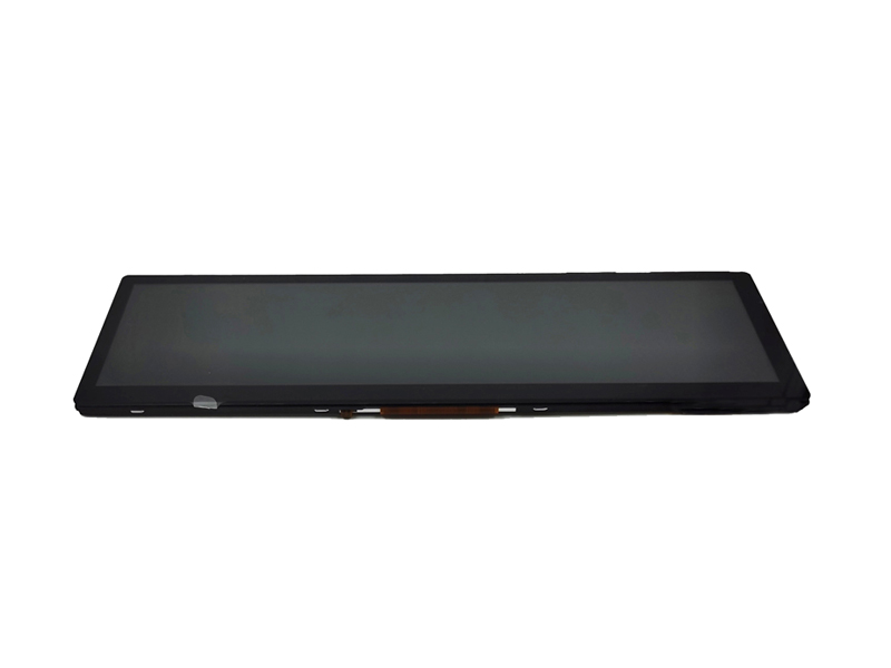
Synchronisation problems rarely appear on the first day. Two bar displays showing a continuous message look perfect at installation and visibly misaligned a week later, because their internal clocks differ by a few parts per million. Whether that matters depends on what the content does across the boundary – and that is a decision to make before specifying the network, not after the first store complains.
Part of the Bar-Type & Stretched Displays guide — 14 articles on aspect ratios, interfaces and multi-bar networks.
What synchronisation means across a multi-screen wall
Aligned pixels, aligned frames or aligned content.
Three levels of alignment are possible and they cost very different amounts. Content alignment means each screen shows a sensible, independent piece of information – prices, labels – and small timing differences are irrelevant. Frame alignment means screens show the same frame of the same video at the same instant, which is what a seamless moving image across several panels requires. Pixel alignment means the physical pixel grids line up so that an image spanning two panels has no visible discontinuity, which is mostly a mechanical issue.
The specification should state which level is required for each content type. Most retail shelf applications need only content alignment; transit bands with scrolling text often need frame-level behaviour, because that is where drift is visible.
Frame-level vs content-level alignment
The content decides the budget.
| Content type | Required alignment | Practical approach |
|---|---|---|
| Prices and labels | Content | Independent units with scheduled updates |
| Scrolling message across a run | Frame or near-frame | Single source with distribution, or shared timing reference |
| Animation spanning several panels | Frame with tight tolerance | Genlock or a synchronised cascade architecture |
| Static information band | Content | Any architecture that meets the update deadline |
Choosing frame-level alignment where content-level alignment would do adds cost throughout the system: a synchronised source, matched firmware and calibration procedures. Choosing content-level alignment where the content spans panels produces visible drift that no amount of content design fully hides.
Clock drift, V-sync and refresh mismatch
Two free-running displays will diverge, always.
Each display has its own oscillator, and oscillators differ from each other and drift with temperature. Two units started together at the same frame rate will drift apart by the tolerance of their own clocks, which is typically a few tens of parts per million – invisible per second, but a whole frame in a few hours. Refresh-rate mismatch adds a second effect: if one panel runs at a slightly different rate, its scaler will periodically repeat or drop a frame, producing a visible hitch even when the average rate is the same.
The engineering answer is either a common timing reference or a content design that does not depend on alignment across panels. CDTech’s notes on display timing parameters cover the terminology that appears in these discussions.
Daisy-chain bandwidth limits and cable length
Cascade interfaces have a budget, and it is finite.
A cascade or daisy-chain connection passes the signal through each unit, so every display adds a small delay and consumes a share of the link budget. Long chains accumulate latency and can exceed the link’s capability, especially with high resolution or high frame rates. Cable length matters in the same way: each segment adds loss and jitter, and the practical maximum depends on the interface and the cable quality.
Serialiser-based links are commonly used where long runs and multiple nodes are needed, because they carry video and control over a single pair with predictable behaviour, as described in the device documentation for products such as TI’s FPD-Link devices. Where a chain is not practical, a distribution architecture with one source per segment is often simpler.
Genlock, signal distribution and external timing
One source, many displays, one clock.
Where frame-level alignment is required, the options are genlock – locking each display’s timing to a common reference – or a distribution architecture where a single source generates the content and each display receives an identical signal with a fixed, matched delay. Both approaches require displays that accept the reference or the signal in the same way, which is why matched units from a single supplier are used in these installations.
For timing-sensitive work the LVDS and serial link design guidance published for components such as those described in TI’s LVDS application note is a useful reference for the electrical constraints. Signal-chain options for distribution and timing are also documented by Analog Devices and by vendors such as STMicroelectronics.
Firmware and scaler differences across units
Mismatched firmware is a hidden synchronisation fault.
Units produced at different times can carry different firmware or different scaler configurations, and either can change the delay between input and display by a frame. That produces a system where most units align and one does not, which is difficult to diagnose from the store floor. The specification should require a single approved firmware version across the installation, a documented procedure for updating units in the field, and a check that the update preserves the timing behaviour.
Where units are replaced over time, the replacement must be configured to the same firmware and settings as the rest of the run. Keeping the configuration record with the installation documentation is simpler than rediscovering it during a service call.
Failure behaviour when one panel drops out
The failure of one unit should not break the run.
In a cascade architecture, a single failed unit can interrupt the chain and darken everything downstream, which turns a small fault into a store-wide outage. Where that risk matters, the architecture should be designed so that units can be bypassed – either physically with a loop-through that passes the signal when unpowered, or logically by using independent sources per segment. The specification should state what happens when a unit loses power, loses video or loses network connectivity, and what the neighbouring units display.
Retaining the last known content on loss of signal is usually the preferable behaviour, particularly for price displays where a blank strip causes a manual check.
Diagnostics and remote monitoring
Alignment problems should be detectable without a site visit.
Useful diagnostics report each unit’s status, the firmware version, the measured input timing and any frame drops or resyncs. Where a system must maintain alignment, a periodic check – comparing a test pattern’s arrival time across units, for example – catches drift before it becomes visible to customers. For a large estate, the operational value of this telemetry is high, because the alternative is a technician walking the aisles with a stopwatch.
Define which metrics are collected, how often, and what triggers an alert. Telemetry that nobody acts on is cost without benefit.
Content design that hides small timing errors
Content can be designed to tolerate drift.
Where frame-level alignment is not justified by cost, content can be designed so that small timing differences do not matter: a repeating message per unit, a per-shelf layout, a colour band, or a gradient that continues visually without requiring continuity of position. The design rule is that no element should span a panel boundary unless the system can guarantee alignment, and no moving element should depend on a fixed relationship with a neighbouring unit.
This is usually the cheapest solution to the problem, and it is a content decision made at the design stage rather than a hardware decision made afterwards.
Test procedure before a store-wide rollout
Test drift over days, not minutes.
- Install a representative run with the final architecture and the approved firmware on every unit.
- Display a pattern that makes a one-frame offset obvious across a boundary.
- Record the offset at installation, after 24 hours and after a week.
- Power-cycle one unit and confirm it returns to alignment within the specified time.
- Disconnect one unit and observe the behaviour of its neighbours and downstream units.
- Verify that an update pushed to the run leaves the alignment unchanged.
This procedure takes a week of elapsed time and answers the question that determines whether the architecture is acceptable. CDTech’s notes on interface selection before design freeze and on bar display cutout and bonding cover the related decisions that are fixed earlier. Interface specifications referenced in these designs are published by MIPI and HDMI.
FAQ
Why do daisy-chained displays drift apart?
Each display runs on its own oscillator, and small frequency differences accumulate into whole-frame offsets over hours. Refresh-rate mismatch adds a second, more visible effect when a scaler periodically repeats or drops frames. A shared timing reference or a matched distribution architecture removes the drift.
How do you keep multiple displays in sync?
Either lock every display to a single timing reference, or distribute one signal to all units with matched delays, and keep firmware identical across the installation. Where the content does not span panels, designing content that tolerates small offsets is usually cheaper than frame-level synchronisation.
What happens if one display in a chain fails?
In a simple cascade, a failed unit can interrupt the downstream signal and darken the rest of the run. Architectures differ: some pass the signal through when unpowered, others use independent sources per segment. Specify the behaviour on power loss and the resulting state of neighbouring units.
How long should a synchronisation test run before rollout?
At least a week, with measurements at installation, after 24 hours and at the end, using a pattern that makes a one-frame offset visible. Add a power-cycle test and a test of what happens when one unit is disconnected, since those are the conditions that reveal architectural weaknesses.
Next step
Send the run length, content type, panel format and required alignment level to CDTech; the reply will describe the achievable synchronisation approach, interface options and the units-per-run limits for that configuration.
Contact sales@cdtech-lcd.com or use the contact page; bar-type formats and interfaces are listed under bar-type LCD displays.
Related articles
 Shelf-Edge Displays for Retail: Brightness, Refresh and Total Cost of OwnershipBar-Type & Stretched Displays
 Cut-Glass vs Native Bar Displays: Which One Survives a Real DeploymentBar-Type & Stretched Displays2.9 Inch 320×120 Bar TFT: Specs, Interfaces, and Use CasesBar-Type & Stretched Displays
 Custom Bar Display Design: Cutout, FPC, and Bonding ChecklistBar-Type & Stretched Displays