Display Interface Selection By Resolution and Refresh Rate: Engineering Checks Before Design Freeze
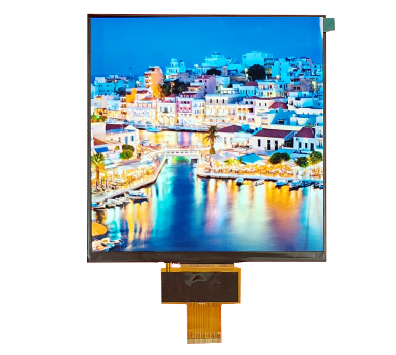
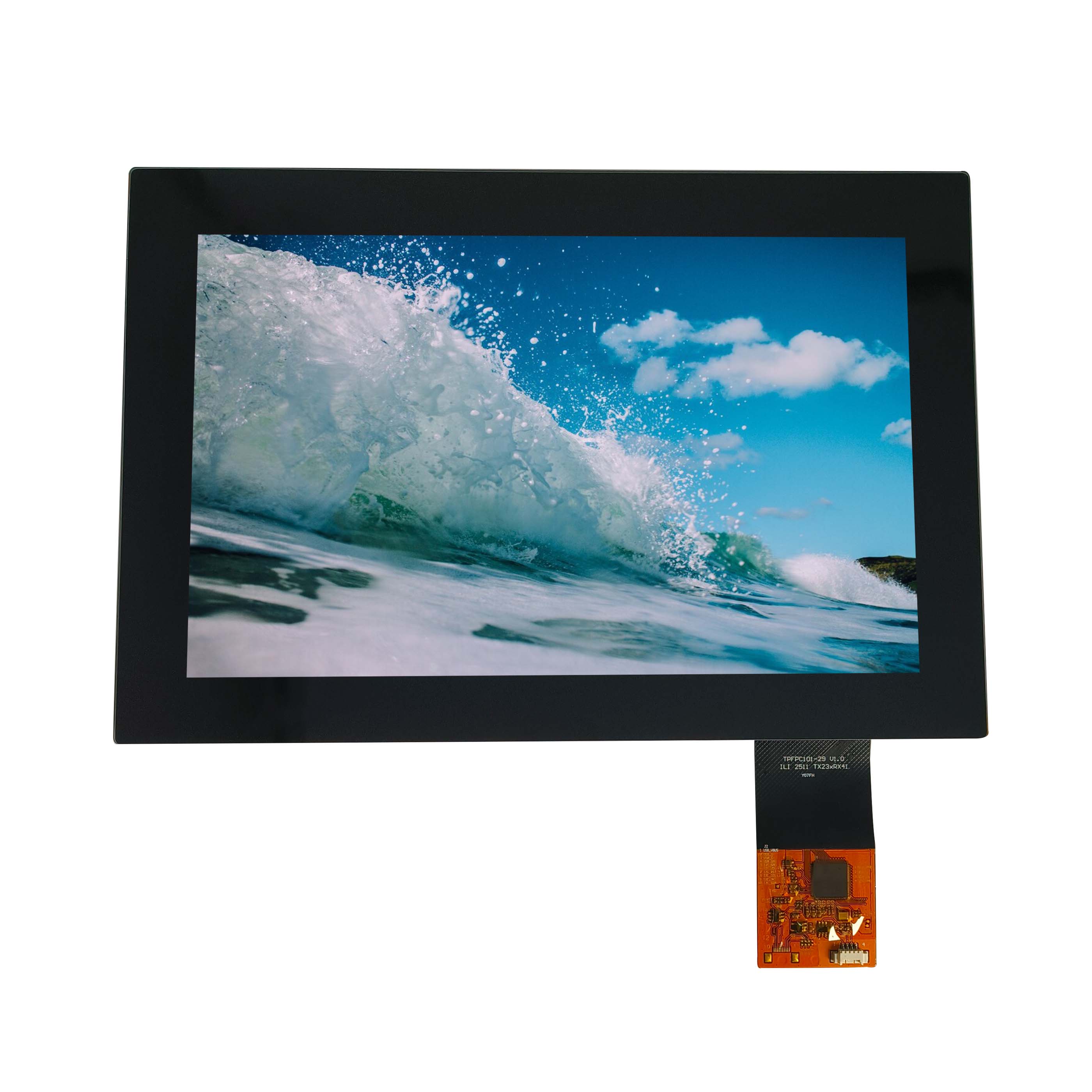
Resolution and refresh rate establish the scale of a display data path, but they do not select an interface by themselves. The decision also needs color format, timing overhead, lane or bus configuration, host…
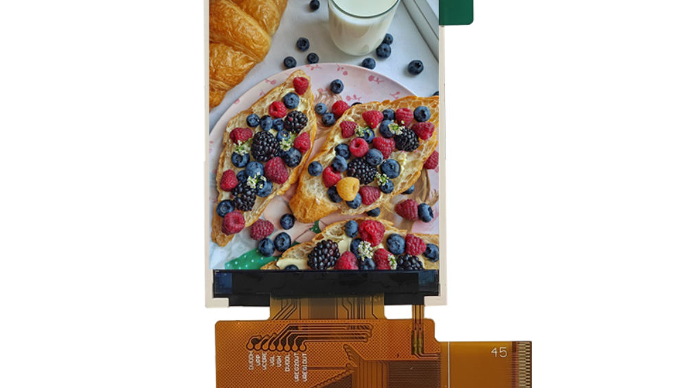
Resolution and refresh rate establish the scale of a display data path, but they do not select an interface by themselves. The decision also needs color format, timing overhead, lane or bus configuration, host support, cable/routing constraints and the panel’s documented input.
Convert the visual requirement into a data-path requirement
Start with native active resolution, intended refresh behavior and pixel format. Add the timing required by the selected panel rather than calculating from active pixels alone. Use controlled host and panel documentation to check whether the complete path can sustain the result.
For partial-update interfaces, include the changed area and update deadline. For continuous-video interfaces, the host must maintain the stream. The article intentionally provides no generic throughput limit because implementation and protocol conditions differ.
Eliminate paths the host cannot generate
List native host outputs, supported modes, available lanes or pins, voltage, clocking and software support. A bridge can translate formats, but it adds configuration, power, PCB area, sourcing and validation work. Use it only when the resulting path is controlled.
Check the panel-side details
Verify interface type, channel or lane count, mapping, timing, color depth, connector, pinout and power/reset behavior. Resolution matching does not prove electrical compatibility. Preserve the existing LVDS-versus-MIPI owner as comparison context; this support article owns the resolution/refresh-rate sizing task only.
Consider routing and cable conditions
Parallel buses may require more pins and matched routing; serialized differential links can reduce pin count but need appropriate layout, impedance and signal-integrity controls. Cable length, connectors, grounding and the enclosure environment can change the practical choice.
Account for processing and scaling
If a controller or scaler changes input resolution, refresh or format, verify both sides. Check buffering, latency, frame behavior and output timing with representative content. Do not assume a board’s accepted input modes equal its supported raw-panel outputs.
Validate before freeze
Prototype the intended host, bridge/controller, cable and module. Check startup, native patterns, color mapping, gradients, motion, update stability, sleep/wake and recovery. Record exact revisions and configuration. Reopen the choice if resolution, refresh behavior, color format, cable or processor changes.
Next step
Review CDTech custom LCD display solutions, then provide the host output, native resolution, refresh requirement and physical connection constraints for a compatibility discussion.
Compare interfaces without generic rankings
Build the comparison from the actual host and panel candidates. For every path, record supported timing, required conversion, physical lanes or pins, PCB constraints, cable environment, software ownership and validation burden. Do not rank interfaces as universally faster or better; a documented native path can be safer than a theoretically capable path that depends on unsupported configuration.
Failure modes and checks
Insufficient or incorrectly calculated data capacity can produce unstable frames or prevent the mode from starting. Mapping and timing errors can show as wrong color, shifted content or intermittent images. Signal-integrity problems may appear only with the production cable or enclosure. Scaling may meet resolution requirements while degrading the real UI. Assign each risk a document review and representative test.
Design-freeze record
Freeze the host output, panel input, timing source, bridge or controller revision, cable, mapping and software configuration. Keep the calculation assumptions and rejected paths. This record prevents a later part substitution from being treated as a connector-only change.