ESD Protection for Display Interfaces
ESD protection for display interfaces: where strikes enter, what actually fails, which parts to specify and how to test to IEC 61000-4-2 without guesswork. | Target URL: https://blog.cdtech-lcd.com/display-esd-protection/

A display fails from static discharge in a way that rarely looks like a static event. A touch controller stops responding after a customer walks across a carpet, a panel that passed every bench test returns from the field with a dead lane, or a unit that works all winter fails in a dry room in February. Protecting the interface means knowing where the strike enters, which part absorbs it and how to prove the answer.
Part of the Interfaces, Touch & Signal Integrity guide — 39 articles on RGB, SPI, LVDS, MIPI, eDP and the touch controller.
What does ESD stand for?
Electrostatic discharge: a sudden charge transfer.
ESD is the abrupt flow of stored static charge between two bodies at different potentials, typically peaking in nanoseconds and carrying currents of several amperes at thousands of volts. In a display assembly the charge arrives through the cover glass, the metal bezel, an exposed connector or a cable shield, and it leaves through whatever path to ground is easiest. The reference practice for handling and testing is published by the EOS/ESD Association.
Where ESD enters a display assembly
Four entry points, ranked by exposure.
The user-facing surface comes first: a finger touching an ungrounded cover glass couples charge directly onto the sensor, and an ungrounded bezel holds it. The connector comes second, especially when a cable is plugged or unplugged while the unit is live. The cable shield follows, because a long harness behaves as an antenna and delivers a strike inside the enclosure. Finally, the mounting points and any external metal bring charge to the chassis.
Each entry point needs a different answer: the surface needs a defined return path, the connector needs clamping, and the harness needs a controlled shield termination.
What actually fails
The controller and the interface, less often the glass.
The most common outcomes are a latched touch controller that needs a reset, a driver or receiver input damaged by a surge that exceeded its absolute maximum, and a shift in the touch baseline that firmware interprets as a permanent touch. Panel glass rarely fails directly. Because the failure is often a latch rather than a burn, it can pass on the bench and return from the field, which is why the recovery behaviour matters more than the pass mark.
Recording where the unit recovers, whether a power cycle is needed and how long the disturbance lasts turns an intermittent complaint into a testable condition.
Interface level protection: what to add
Place the clamp where the strike arrives, before the IC.
Protection belongs on every conductor that leaves the enclosure: the touch interface lines, the display data lanes, the backlight control and any exposed I2C or SPI. TVS diodes or other clamping devices should be chosen for their working voltage, their clamping voltage and their capacitance, because capacitance on a high-speed differential lane changes the signal integrity that the interface was chosen for. On the fastest lanes, the protection is often a low-capacitance array placed within a few millimetres of the connector.
The rule that saves most designs is simple: the protection device sits between the connector and the circuit, with a short, wide return to the ground plane. Long return loops make a good clamp useless.
Protection at the connector and in the cable
The connector is the most exposed conductor in the system.
Where the design allows it, a shielded connector with a defined shell-to-chassis bond sends most of the strike straight to the enclosure rather than through the signal pins. Where the connector must be unshielded, series resistance and a clamp on each exposed line limit what reaches the device. Stress testing for the assembly as a whole follows the same family of standards used for enclosures, including IEC 60529 for ingress and ASTM B117 for salt-spray exposure of metal parts.
Protection at the touch panel and cover glass
An ungrounded front is an antenna, not a barrier.
A capacitive touch panel depends on coupling between the finger and the sensor, which means the cover glass has no shielding role at all. The route to a robust front is to give the assembly a low-impedance path from the sensor’s reference to the chassis, to keep the bezel at the same potential as the system ground, and where the product demands it to add an optically transparent conductive layer tied to ground. Each of those adds cost or reduces optical transmission, so the decision belongs in the requirement rather than the fix.
The practical test is to hold the assembled front at a defined charge and confirm that the touch baseline returns without a power cycle.
Grounding, shielding and the return path
Protection works only if the return is defined.
A clamp diverts energy into the ground system, so the ground system has to carry it without raising the local potential that the silicon sees. That means a continuous reference plane under the interface, a chassis bond that is short and wide rather than a thin wire, and a single defined point where the digital return and the chassis meet. Splitting ground without a defined tie turns a two-layer problem into a resonant one, and the symptom is a unit that fails only when a specific cable is attached. The mechanics of that path are treated alongside grounding and shielding design for display modules.
System level test practice
Test the finished product, at the points a user can touch.
The accepted method applies a defined discharge to the enclosure and to the connector, at several voltage levels, with the product powered and running its firmware. The product is the unit under test, not the panel, because the housing, the gasket and the cable all change the result. A useful run records three things per point: whether the image disturbed, whether the touch recovered, and whether the change persisted after the strike. Recovery without a power cycle is the acceptance criterion that separates a robust design from a lucky one, and the safety context for the equipment is set by IEC 62368-1.
What to specify on a datasheet
Six lines prevent most arguments.
- The discharge levels the module is expected to survive, with the test standard referenced.
- The protection devices fitted on the module, if any, with their capacitance.
- The recommended ground and chassis bonding for the front and the connector.
- The touch recovery behaviour expected after a strike, with and without a power cycle.
- The connector family and whether it is shielded.
- The firmware version used for the evaluation.
Manufacturing and inspection expectations for the electronics that carry those parts are published by IPC, and laboratory competence can be checked through accreditation bodies such as the International Accreditation Forum.
Incoming inspection and supplier evidence
Ask for the fixture, not just the result.
An ESD claim is only as good as the setup behind it. A supplier report should name the standard, the levels, the number and location of discharge points, the product configuration and the pass criterion. A report that states a single voltage with no fixture description cannot be reproduced. Where the front is supplied as a bonded assembly, the report should cover the bonded unit, because the adhesive and the cover glass change the coupling that the test is measuring.
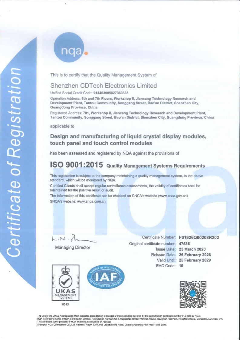
The same discipline appears in CDTech’s quality assurance and factory compliance material and in the display and touch solutions centre.
FAQ
What is ESD an acronym for?
Electrostatic discharge: the sudden transfer of static charge between two bodies at different potentials. It peaks in nanoseconds and is measured in kilovolts and amperes, which is why a discharge that a person barely feels can damage an unprotected interface.
What does ESD stand for shipping?
It refers to the packaging intended to protect sensitive parts while they are transported. Such bags and containers dissipate or shield charge so that a module is not damaged by handling before it is installed. It is a handling concern rather than an interface design one.
What does ESD stand for in business?
Outside electronics the acronym is used for other terms, so the meaning has to come from context. In a display or electronics supplier conversation it almost always means electrostatic discharge and the associated control programme.
Where should ESD protection be placed on a display module?
Between the connector and the circuit, within a few millimetres of the point where the strike arrives, with a short and wide return to the ground plane. On fast differential lanes, choose a low-capacitance device so that the protection does not undo the signal integrity the interface was selected for.
Next step
Send the enclosure drawing, the touch and display interfaces and the discharge levels the product must survive to CDTech; the reply will state the recommended protection placement, the grounding scheme and the test points that prove it.
Contact sales@cdtech-lcd.com or use the contact page, or start from the sample and quote request page.
Related articles
 Bring-Up Debugging: No Display, Wrong Colours, Flicker and Everything in BetweenInterfaces, Touch & Signal Integrity
 Industrial Displays in High-EMI Environments: Protecting Signals and TouchInterfaces, Touch & Signal IntegrityFHD Versus IPS: Separating Resolution From Panel TechnologyInterfaces, Touch & Signal Integrity
 Integrating a Touch Sensor With a Display StackInterfaces, Touch & Signal Integrity