Projected Capacitive Touch Panel Design
Projected capacitive touch panel design: sensor pattern, cover glass, bonding, controller tuning, EMC and the specification points that decide success. | Target URL: https://blog.cdtech-lcd.com/projected-capacitive-touch-design/
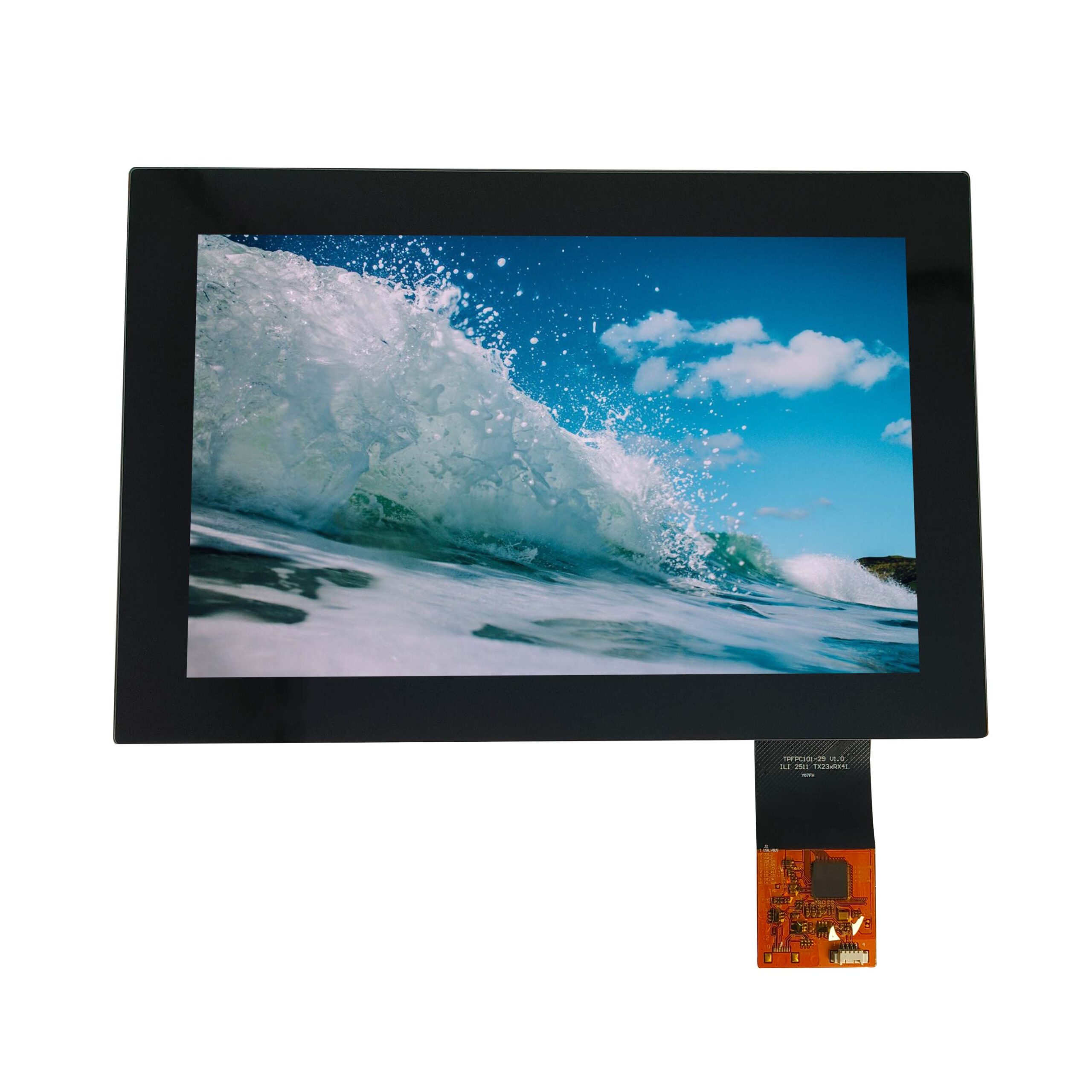
A projected capacitive panel is easy to buy and hard to design well. The sensor, the cover glass, the adhesive and the controller firmware interact, and a change in any one of them moves the others. Most touch problems that reach production are not sensing failures at all; they are stack decisions that were made independently and never reconciled.
Part of the Interfaces, Touch & Signal Integrity guide — 39 articles on RGB, SPI, LVDS, MIPI, eDP and the touch controller.
What is a projected capacitive touch panel?
A sensor that measures capacitance change nearby, not contact.
A projected capacitive, or PCAP, panel places a transparent conductive pattern behind a cover glass and measures the change in mutual or self capacitance when a finger approaches. Because nothing has to be pressed, the surface can be glass, the panel can be sealed, and gestures are possible. A typical medical or industrial front is a sensor laminated to a cover glass and bonded to the display, with the controller on a flex tail. The complete engineering picture is collected in the display and touch solutions centre.
PCAP versus other touch technologies
Capacitive for glass and gestures, resistive for gloves and pens.
PCAP offers multi-touch, a hard and cleanable surface and a long mechanical life, but it needs a conductive input, which is why thick gloves and passive styli are difficult. Resistive panels accept any stylus and work with gloves but wear, and they cannot sense a finger without pressure. The comparison for vehicle HMI is set out in PCAP versus resistive touch for automotive, and the broader trade in the full comparison. Neither wins outright; the input device the user will actually hold decides.
The sensor: pattern, pitch and ITO
The pattern sets accuracy; the pitch sets the smallest gesture.
Mutual-capacitance diamond or bar-and-stripe patterns dominate. Finer pitch improves positional accuracy and small-object detection but raises channel count and controller cost, and it reduces the electrode width, which lowers the signal. Indium tin oxide remains the standard transparent conductor, with metal mesh gaining ground where sheet resistance or flexibility matters. For a given size, the design question is the trade between the number of channels the controller can scan in the time available and the resolution the interface needs.
Edge channels typically see a different baseline from interior ones, which is why linearity is quoted over a defined active area rather than the whole surface.
Cover glass and the optical stack
The front glass is part of the sensor’s environment.
Thicker cover glass lowers the coupling change at the controller, so the design must be agreed with the sensor sensitivity in advance; a 1.1 mm and a 3 mm front are different electrical problems. Surface treatment then sets how the product looks and cleans. Anti-glare scatters reflected light and preserves image contrast with a slight haze, anti-reflective coatings reduce reflection with lower haze, and the practical measurement of both is described in haze, gloss and surface treatment. Haze is quantified by the method in ASTM D1003.
Bonding: OCA, OCR and air gap
Bonding decides contrast, robustness and rework cost.
An air gap is the cheapest option and the worst optically: two extra reflections reduce contrast and trap dust. Optical clear adhesive, supplied as a sheet, gives a controlled thickness and repeatable lamination; optically clear resin, dispensed as a liquid, conforms to curved or uneven surfaces and suits larger formats. Both need a supplier whose process is controlled, because bubbles, mura and delamination are process faults that appear as optical and functional ones. Adhesive behaviour under temperature and UV exposure is documented by the materials houses such as DELO, Henkel and the tape makers such as tesa. The inspection that catches bonding faults is described in inspecting optical bonding quality.
The controller and its tuning
Tuning is state-dependent, not a single number.
The controller’s baseline, threshold and filtering determine how the panel behaves with water on the surface, with a glove, and near a noisy switching supply. Firmware that passes on a bench with a clean supply and a dry finger may fail in a housing where the display backlight is dimmed by PWM. Tuning therefore belongs with the final stack, the final cover glass and the final chassis, and the firmware version should be recorded with the result as the principles in multi-touch sensing make clear.
EMC, noise and the environment
The front is the most exposed conductor on the product.
Because the cover glass carries no shielding, electrical fast transients and discharge reach the sensor directly, and the sensor’s own electrodes can couple noise into nearby circuits. A continuous ground reference under the sensor, a shell-to-chassis bond at the connector, and care with the display drive frequency all reduce the problem. Where the product must survive static discharge at the surface, the practice published by the EOS/ESD Association is the starting point.
Mechanical integration and sealing
The panel must be held without being stressed.
A touch front in a sealed housing has to be gasketed at the glass edge, bonded without trapping stress, and supported so that pressure on the glass does not move the sensor relative to the display. Metal cover glass suppliers such as AGC publish thickness and strength data that feeds the mechanical budget. Where the front has to meet an impact rating, the glass thickness and the mounting method are the two variables, and the trade is between weight, cost and impact energy.
Test and acceptance
Accuracy, edge behaviour and conditions, in that order.
A PCAP acceptance programme covers a defined grid of points for accuracy and linearity, an explicit outer ring for edge behaviour, and repeats with the glove and water conditions the product will meet, with the surface treatment as delivered. Recording a pass rate per point rather than a single verdict is what makes the result repeatable, and the protocol for that belongs with the product’s quality assurance and factory compliance documentation, not in a separate document that nobody references.
What to specify when you order
Nine lines turn a request into a design.
- Active area, cover glass thickness, material and edge treatment.
- Input devices: bare finger, thin glove, thick glove, stylus.
- Number of simultaneous touches required.
- Surface treatment and the haze or gloss target.
- Bonding method: OCA sheet, OCR resin or air gap.
- Controller family, interface and supply voltage.
- Operating conditions including water and cleaning agents.
- Discharge and ingress levels the front must survive.
- The mechanical outline and the sealing method.
FAQ
What is a projected capacitive touch panel?
A transparent conductive pattern behind a cover glass that measures the change in capacitance when a finger approaches. Nothing has to be pressed, so the surface can be sealed glass, several touches can be tracked at once and gestures are possible.
What is PCAP in a touch panel?
PCAP is the common abbreviation for projected capacitive. It distinguishes the electrode pattern behind the glass from surface capacitive, which uses a uniform coating and supports only a single touch.
What are the downsides of a capacitive touch screen?
A conductive input is needed, so thick gloves and passive styli are difficult; water on the surface can be interpreted as a touch; and the front offers no shielding for static discharge. Each has a design answer, but each has to be specified rather than assumed.
Which is better, resistive or capacitive touch?
Capacitive suits sealed glass fronts, multi-touch and long life with fingers and thin gloves. Resistive suits any stylus, heavy gloves and the lowest possible cost, at the price of a softer, wearing surface and no true multi-touch.
Next step
Send the active area, the cover glass, the input devices and the environment to CDTech; the reply will state the sensor and controller choice, the bonding method and the test points that confirm it.
Contact sales@cdtech-lcd.com or use the contact page, or start from the sample and quote request page.
Related articles
 Bring-Up Debugging: No Display, Wrong Colours, Flicker and Everything in BetweenInterfaces, Touch & Signal IntegrityIndustrial Displays in High-EMI Environments: Protecting Signals and TouchInterfaces, Touch & Signal IntegrityFHD Versus IPS: Separating Resolution From Panel TechnologyInterfaces, Touch & Signal IntegrityIntegrating a Touch Sensor With a Display StackInterfaces, Touch & Signal Integrity