Custom Bar Display Design: Cutout, FPC, and Bonding Checklist
Custom bar displays are built around the product's enclosure, not the other way around. The enclosure defines the active-area position and the cutout; the display design then answers how the glass is cut, how…
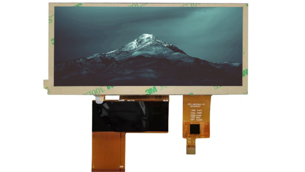
Starting From the Enclosure: Active Area and Bezel
Begin with the enclosure: the available opening, the bezel width, and where the active area must sit. These define the display’s outline, the active-area position, and the tolerances the module must hold. Freeze the mechanical envelope first—every later decision (cutout, FPC, cover) hangs off it.
Custom Cutout: Tolerances, Edge Sealing, and Uniformity
If the bar needs a custom width or shape beyond standard formats, the panel may be cut to size. Custom cutting changes the edge condition: cut edges need sealing, tolerances tighten, and the risk of light leakage or stress damage rises near the cut. Verify the achievable tolerance and the edge-sealing method with the supplier before committing, because cut quality decides both appearance and long-term reliability.
FPC Design: Length, Pitch, and Bend Radius
The FPC connects the bar to the host, so its length, exit direction, pitch, and bend radius must match the mechanical routing. Longer FPCs and tighter bends stress the copper and raise signal-integrity risk. Define the route and connector position in the mechanical design, then confirm the FPC design rules with the supplier—the generic FPC signal-integrity guide covers the electrical side of this decision.
Cover Glass Options: Thickness, Coatings, and Cutouts
A cover protects the bar and carries the optical finish. Choose thickness from the impact and touch requirements, coatings (AG/AR) from the viewing environment, and cutouts to match the enclosure. Cover design decisions follow the general cover glass guide; the bar format adds width-related constraints such as edge strength on long, narrow glass.
Bonding and Touch Options for Custom Bars
Bonding the cover to the bar improves sunlight readability and strength; touch, where needed, is usually PCAP and must match the bar’s active area. The structural bonded-versus-air-gap decision and the OCA-versus-OCR material choice each have their own guides; for a custom bar, the long, narrow geometry affects both the bonding process and the touch sensor layout.
Prototype Verification: Samples, Revisions, and Metrology
The custom design is only real when measured. Verify the first samples against the drawing: outline, active-area position, cutout dimensions, FPC route, and cover fit, plus optical and functional checks. Log deviations, agree revisions with the supplier, and re-verify—the prototype round is where custom-bar problems surface cheaply, before tooling locks the design.
Frequently Asked Questions
What tolerances matter for a custom bar cutout?
Outline dimensions, active-area position, cut edge quality, and edge-sealing integrity. Confirm the achievable tolerances with the supplier before tooling.
How is a bar display FPC designed?
Define the route, length, exit direction, and connector position from the mechanical design, then apply FPC design rules for pitch, bend radius, and signal integrity.
What cover glass options work for bar displays?
Flat covers in the bar’s width with optional AG/AR coatings and cutouts; long, narrow glass needs attention to edge strength and handling.
How is a custom bar display bonded?
With the same bonding options as other displays—air gap, OCA film, or OCR resin—chosen by geometry and readability needs; the bar’s long, narrow shape affects process and yield.
If you are designing a custom bar display, start from the enclosure and freeze the mechanical envelope before the cutout, FPC, and cover decisions. CDTech supports custom bar display design across the bar-type LCD range—contact us with your enclosure drawing.