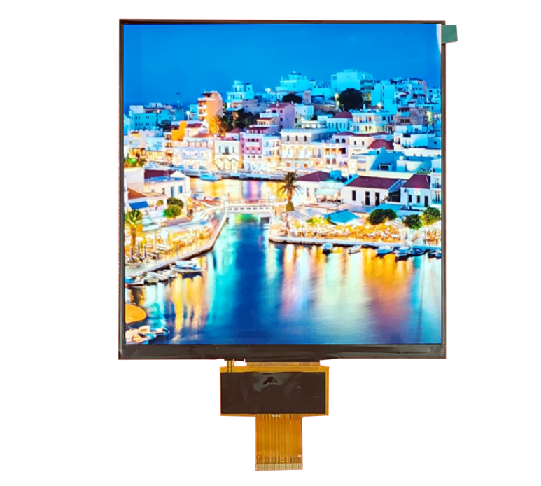
FPC Cable Design for Displays: Preventing Flicker and EMI
The flexible printed circuit (FPC) that connects a display to its host looks like a simple ribbon, but it carries high-speed signals through a mechanically stressed part. A poorly designed FPC produces flicker, interference,…

Why FPC Design Matters: Signal Integrity and Mechanical Life
An FPC has two jobs at once: it must carry clean electrical signals and survive repeated flexing for the life of the product. Failure in either job looks like a display problem:
- Signal integrity failure — noise or impedance mismatch corrupts data lines, producing image glitches or flicker that can be intermittent and temperature-dependent.
- Mechanical failure — cracked copper, lifted pads, or broken solder joints at the connector create open or marginal connections.
Both failure modes are design issues: they are decided by routing, materials, and assembly constraints long before the FPC reaches your production line.
Bend Radius and Stiffeners: Protecting Copper in Assembly
Flexible copper is strong until it is bent too tightly or repeatedly at the same point. Three rules protect it:
- Respect the minimum bend radius — the datasheet or the FPC manufacturer’s design rules define how tightly the flex can bend; tighter bends stress the copper and shorten life.
- Keep bends out of solder and pad areas — flexing near solder joints concentrates strain on the connection; transition zones need length before a bend.
- Add stiffeners where the FPC is handled — stiffeners at the connector end and under components prevent the copper from flexing at the joint during assembly and use.
If the product flexes the FPC repeatedly (a moving display, a folding product, a door harness), flex-life testing with the real bend cycle is part of the design, not an afterthought.
Ground and Shielding: Preventing Flicker and EMI
Flicker caused by the FPC is usually a grounding or shielding problem. High-speed display signals return through ground; if the return path is broken or shared with noisy lines, the signal degrades and the image flickers. Practical design rules:
- Provide continuous ground — dedicated ground traces or a ground plane area under the signal lines give signals a clean return path.
- Keep sensitive lines away from switching noise — clock and data lines should not run beside backlight or power-switching traces that inject noise.
- Use shielding where needed — for EMI-sensitive products, an outer ground layer or shield film contains radiated emissions.
Not every flicker is signal-integrity flicker: backlight dimming (PWM/DC) causes its own flicker, and controller timing issues cause their own artifacts. Those causes have separate owners; this article covers the FPC signal path.
Connector Selection: Pitch, Locking, and Plating
The connector is the most failure-prone part of the display interconnect. Selection criteria:
- Pitch and footprint — smaller pitch saves space but increases assembly and alignment sensitivity; choose the smallest pitch your factory can reliably handle.
- Locking mechanism — vibration and handling can loosen a non-locking connector; use a lock or latch in mechanically stressed products.
- Plating and contact design — gold or other robust plating resists corrosion and fretting in humid or high-cycle environments.
Connector choice also interacts with the FPC pad layout and stiffener design, so select the connector before finalizing the FPC, not after.
Testing the FPC: Impedance, EMI Pre-Scan, and Flex Life
Design rules reduce risk; tests prove the result. The three tests that matter most:
- Impedance verification — for controlled-impedance differential pairs, measure the actual impedance and confirm it matches the design target across the FPC length.
- EMI pre-scan — run the display with the FPC in the product configuration and scan for radiated emissions before formal compliance testing.
- Flex-life testing — cycle the FPC through the real bend motion and verify electrical continuity and image stability after thousands of cycles.
Test methods and pass levels come from your product requirements and applicable standards; treat the descriptions here as the test categories to specify, not as universal limits.
Working With the Supplier: Co-Designing the FPC
FPC design is a collaboration between the display module supplier and your mechanical team. Bring to the table:
- The mechanical path — routing, bend location, bend radius, and how the FPC is anchored in the product.
- The electrical environment — which signals run where, and what noise sources sit nearby.
- The connector preference — pitch, locking, and plating based on your assembly and environment.
- The test expectations — flex life, impedance, and EMI requirements before the first prototype.
A supplier that asks for the mechanical path and noise environment early is designing an FPC; one that only asks for a pin count is quoting a ribbon. Work with the former, and validate with samples before freezing the design.
Frequently Asked Questions
Can a bad FPC cause display flicker?
Yes. Broken or noisy signal return paths, poor grounding, and shielding gaps on the FPC can degrade display signals and produce flicker or image glitches.
What bend radius should an FPC use?
The minimum bend radius comes from the FPC manufacturer’s design rules and the copper stack. Keep bends out of solder and pad areas, and add length before transition zones.
Why does FPC shielding matter for EMI?
High-speed display signals radiate from unshielded flex. A ground layer or shield film contains the field and provides a clean return path, reducing both emissions and susceptibility.
How is FPC impedance tested?
With a time-domain reflectometer or impedance analyzer on the fabricated flex, measuring the actual impedance of controlled traces against the design target.
If your display interconnect is flexed, routed near noise, or EMI-sensitive, define the mechanical path and signal environment early. CDTech co-designs FPC and display modules for custom projects—contact us with your routing constraints to discuss the design.