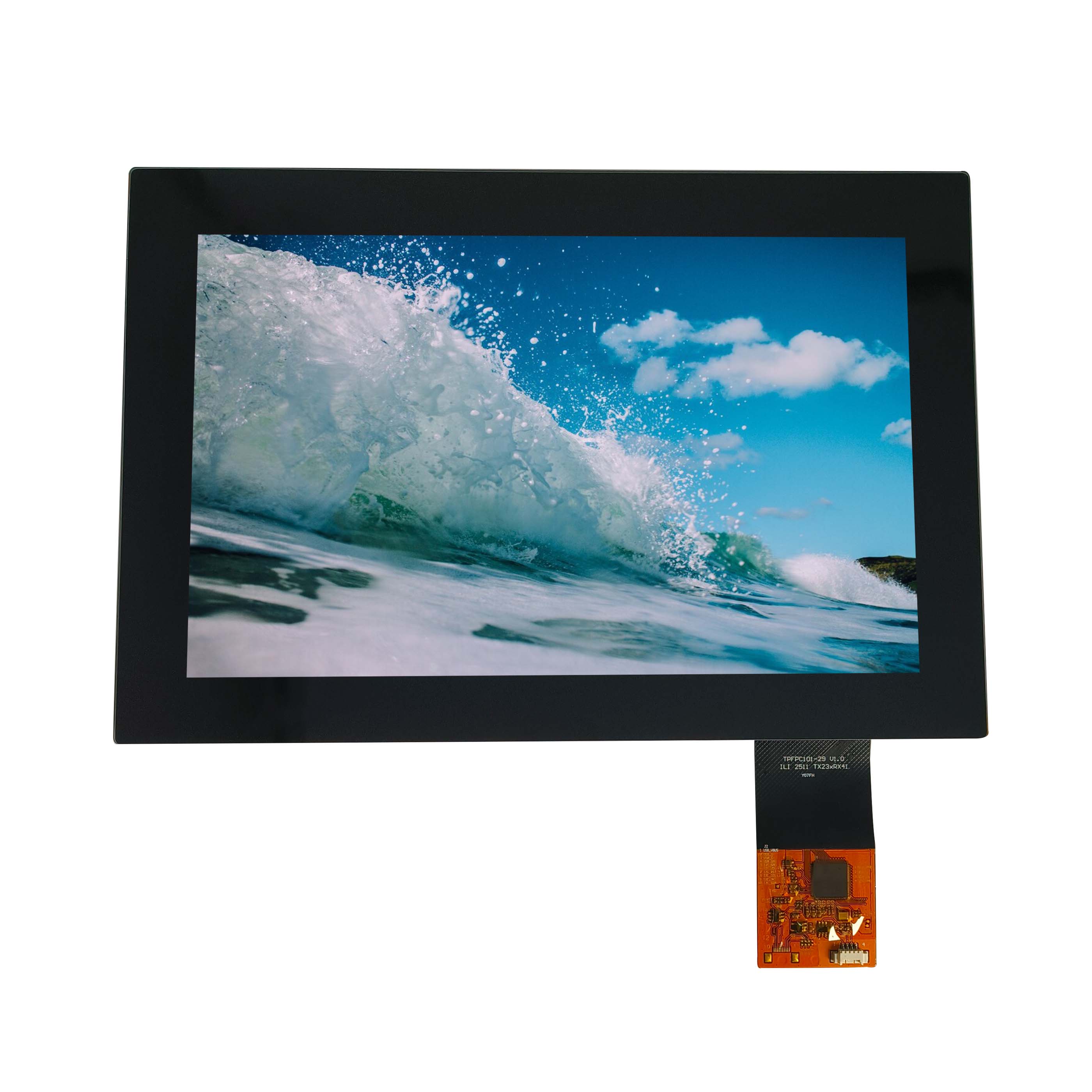
How to Port Linux and Android Automotive Touch Drivers?
Linux and Android touch driver porting connects a custom automotive touch module to a vehicle SoC board by aligning hardware wiring, kernel configuration, Device Tree nodes, input-event reporting, and coordinate transforms. Reliable integration depends…

Linux and Android touch driver porting connects a custom automotive touch module to a vehicle SoC board by aligning hardware wiring, kernel configuration, Device Tree nodes, input-event reporting, and coordinate transforms. Reliable integration depends on correct I2C/SPI timing, reset and interrupt GPIO definitions, panel-resolution mapping, Android input configuration, and production-level validation across temperature, sleep, and multi-display states.
What Makes Automotive Touch Driver Porting Different?
Automotive touch driver porting is harder than consumer-tablet integration because the touch controller must remain stable through fast boot, suspend/resume, EMI exposure, temperature cycling, multi-display routing, and long vehicle service life.
A custom touch module is not merely an I2C peripheral attached to a display. It is an input subsystem device whose electrical behavior, firmware version, coordinate space, power sequence, and operating-system configuration must agree.
In production projects using Qualcomm 8155/8295, Renesas, and NXP platforms, the most expensive failures usually do not come from compiling the driver. They come from assumptions made between teams:
- The display team assumes portrait coordinates.
- The Android UI team assumes landscape coordinates.
- The PCB team routes an interrupt GPIO with a pull direction different from the controller requirement.
- The touch vendor uses a firmware that changes its report format after reset.
- The board-support package enables the driver but omits its regulator or pinctrl state.
- A USB touch controller works at the workbench but fails to enumerate after vehicle cold-crank recovery.
For automotive HMI projects, CDTech normally treats the LCD, cover lens, touch sensor, controller IC, flex cable, and host driver as one validated interface stack. That approach reduces the risk of resolving a display issue only to create a touch-input issue later.
Which Touch Interface Should You Choose?
Choose I2C for embedded automotive touch modules requiring controlled startup and low-pin-count integration, SPI for higher reporting bandwidth or controller-specific requirements, and USB HID for fast plug-and-play deployment where board-level control is less critical.
The interface decision changes the integration work, fault isolation method, and long-term maintenance burden.
| Interface | Best fit | Practical strengths | Common production failure |
|---|---|---|---|
| I2C | Integrated display/touch assemblies | Low pin count, mature Linux support, simple board integration | Address conflict, weak pull-ups, reset/INT timing errors |
| SPI | High-report-rate or controller-specific modules | Higher throughput, deterministic transfer timing | Incorrect mode, chip-select timing, DMA-related transfer faults |
| USB HID | External or modular touch displays | Standard driver support and rapid bring-up | USB brownout, hub enumeration order, connector vibration issues |
I2C remains the most common option for a bonded automotive LCD touch display because it needs only SDA, SCL, interrupt, reset, power, and ground connections. But it is not automatically the cheapest system-level option. A long FPC route near LVDS, eDP, MIPI, or switching regulators can introduce enough noise that extra shielding, pull-up tuning, and debug time outweigh the nominal wiring advantage.
In our vehicle-display integration runs, 100 kHz I2C is often more tolerant during first bring-up, while 400 kHz is usually acceptable after signal integrity is verified. Do not select 1 MHz Fast-mode Plus merely because the controller supports it. On a long harness or a noisy carrier board, the faster bus can turn marginal edge timing into intermittent NACKs that appear only after thermal soak.
USB touch controllers usually enumerate as HID-class devices and can operate without a custom Linux touchscreen driver. However, plug-and-play does not mean zero engineering. Verify that the USB port remains powered during the required ignition transitions, that the USB hub is initialized before the display service starts, and that Android maps the correct HID device to the intended physical panel.
How Should an I2C Touch Node Be Written?
An I2C touchscreen Device Tree node must accurately define the compatible string, I2C address, interrupt source, reset GPIO, power resources, pinctrl configuration, and touchscreen coordinate properties required by the selected kernel driver.
A Device Tree describes fixed hardware that the Linux kernel cannot discover on its own. For a typical I2C touch controller, the compatible property connects the hardware node to the matching kernel driver, while reg specifies the 7-bit I2C address.
&i2c6 {
    status = "okay";
    clock-frequency = <400000>;

    touchscreen@14 {
        compatible = "goodix,gt911";
        reg = <0x14>;

        interrupt-parent = <&tlmm>;
        interrupts = <65 IRQ_TYPE_EDGE_FALLING>;

        reset-gpios = <&tlmm 64 GPIO_ACTIVE_LOW>;
        irq-gpios = <&tlmm 65 GPIO_ACTIVE_HIGH>;

        pinctrl-names = "default", "sleep";
        pinctrl-0 = <&touch_default>;
        pinctrl-1 = <&touch_sleep>;

        touchscreen-size-x = <1920>;
        touchscreen-size-y = <720>;
        touchscreen-swapped-x-y;
        touchscreen-inverted-x;

        vdd-supply = <&vreg_l8a_3p0>;
        vcc_i2c-supply = <&vreg_l5a_1p8>;

        status = "okay";
    };
};
Use this as a configuration pattern, not a copy-and-paste promise. Property names vary by upstream driver and vendor kernel branch. A downstream Qualcomm Android kernel may expose controller-specific properties that do not exist in a mainline driver. Confirm the binding documentation and driver source before finalizing the DTS.
Three details deserve special attention:
reg = <0x14>must match the controller’s actual address after its reset or address-select sequence.- The interrupt trigger must match the hardware waveform. A controller that holds INT low until serviced typically requires level-low behavior; a short active-low pulse usually needs falling-edge behavior.
touchscreen-size-xandtouchscreen-size-yshould describe the controller’s native coordinate range unless the driver documentation explicitly expects panel pixel dimensions.
A common field failure occurs when the touch controller reports 4096 × 4096 raw units, but the DTS is set to 1920 × 720 because that is the display resolution. The result can be clipped edges, non-linear scaling, or incorrect Android calibration. Keep raw reporting range and display mapping conceptually separate unless the driver performs the conversion itself.
How Do You Configure SPI Touch Controllers?
SPI touch configuration requires a correct compatible string, chip-select assignment, SPI mode, maximum clock rate, interrupt/reset GPIOs, and power-state definitions; an incorrect SPI mode can produce valid-looking but corrupted touch packets.
SPI often appears straightforward because there is no address scanning. In practice, the controller can communicate while still returning unusable data if CPOL/CPHA, bit order, transfer length, or chip-select timing is wrong.
&spi4 {
    status = "okay";

    touchscreen@0 {
        compatible = "vendor,automotive-touch";
        reg = <0>;

        spi-max-frequency = <12000000>;
        spi-cpol;
        spi-cpha;

        interrupt-parent = <&gpio>;
        interrupts = <42 IRQ_TYPE_EDGE_FALLING>;

        reset-gpios = <&gpio 41 GPIO_ACTIVE_LOW>;

        touchscreen-size-x = <1920>;
        touchscreen-size-y = <720>;

        pinctrl-names = "default", "sleep";
        pinctrl-0 = <&touch_spi_active>;
        pinctrl-1 = <&touch_spi_sleep>;

        status = "okay";
    };
};
Start conservatively. For an unknown module, begin at 1–4 MHz, confirm stable device identification and event packets, then increase toward the validated operating clock. We have seen a touch controller pass a short lab test at 24 MHz but generate one malformed multi-touch frame every few thousand reports after an 85°C soak. Reducing the bus to 12 MHz removed the errors without perceptibly affecting user interaction.
For SPI, scope MOSI, MISO, SCLK, CS, reset, and INT together during boot. Looking at only SCLK and MISO can hide a chip-select deassertion that splits a report frame into two transactions.
Why Do Touch Coordinates Become Mirrored?
Touch coordinates become mirrored, swapped, offset, or scaled when the controller coordinate system, LCD scan orientation, compositor orientation, and Android input mapping use different reference points or rotation assumptions.
A 12.3-inch automotive display mounted in landscape may use a touch sensor physically manufactured in portrait orientation. The LCD panel may be mounted upside down to satisfy cable routing. Android may then render a rotated UI. If each layer applies a correction independently, a single physical touch can be rotated twice.
Most basic cases can be solved with standard Device Tree properties:
touchscreen-swapped-x-y;
touchscreen-inverted-x;
/* touchscreen-inverted-y; */
Use only the transforms that are physically required. Do not enable swap and inversion because “it feels close.” Establish the coordinate chain first:
- Capture the controller’s raw minimum and maximum X/Y values.
- Confirm the panel’s native pixel orientation.
- Confirm whether the display pipeline rotates the framebuffer.
- Apply a transform at one deliberate layer.
- Validate all four corners, center points, swipes, and multi-touch gestures.
For a 1920 × 720 display, test at least these positions: near (20,20), (1900,20), (20,700), (1900,700), and center. Avoid testing exactly at the edge because palm rejection and bezel dead zones can make a correct mapping look incorrect.
In Android, kernel-reported events flow through the Linux input protocol and then Android’s input system. Android can use input-device configuration files to apply calibration and transforms. The cleanest production design is usually to keep controller-specific orientation in the kernel or Device Tree, then reserve Android configuration for display association, scaling, and deployment-specific policy.
What Is the Best Multi-Display Mapping Method?
The best multi-display touch mapping method assigns each touch device to a stable physical display identity, validates its independent coordinate domain, and applies display-specific transforms without relying on boot-order-dependent device names.
A dual-display cockpit may include a center information display and an instrument display, each with its own touch controller. The hard part is not detecting two /dev/input/event* nodes. The hard part is ensuring the correct input device remains associated with the correct display after a kernel update, USB hub reset, or controller replacement.
For Android-based systems, create a deterministic identity through the input device name, vendor/product identifiers where available, and matching configuration files. Avoid binding logic to /dev/input/event2 or /dev/input/event5; event numbering is not stable.
In factory validation, use a physical target grid on each screen. A practical grid is 5 × 3 points for a 1920 × 720 panel and 3 × 5 points for a 720 × 1920 panel. Log the reported raw coordinates and final UI coordinates. This exposes three problems that a basic corner test misses:
- Non-linear distortion from an incorrect calibration matrix.
- A stale configuration file loaded for a similarly named controller.
- Cross-screen routing that occurs only after display hotplug or suspend/resume.
CDTech recommends defining touch/display pairing during platform architecture, before the housing and cable layout are frozen. A late change from one shared controller to two independent controllers can affect connector count, FPC routing, electromagnetic performance, and software validation scope.
Can Dynamic Calibration Improve Automotive Accuracy?
Dynamic calibration can improve touch accuracy when panel mechanics, cover-lens stack-up, operating temperature, or controller firmware create repeatable coordinate drift, but it cannot fix noise, incorrect orientation, or unstable I2C/SPI communication.
Calibration should not be a substitute for correct mechanics. If the touch stack moves relative to the LCD because of poor bonding or thermal expansion, a software matrix may hide the issue at room temperature and fail at temperature extremes.
Use dynamic calibration only when measurements show a stable, repeatable error pattern. For example, if a 15.6-inch display consistently shifts by 6–10 pixels on the far-right edge after a known thermal state, a controlled correction may be appropriate. If the error randomly changes from 2 pixels to 45 pixels, investigate electrical noise, grounding, firmware reports, or mechanical stress instead.
A useful calibration workflow includes:
- Raw coordinate capture before any Android-side transform.
- A defined test grid with measured touch offsets.
- Separate data sets at room temperature and thermal limits.
- Version control for firmware, DTS, input configuration, and display timing.
- A rollback path for calibration packages in field service.
Do not calibrate using a finger alone when validating a production line. Finger contact area and pressure vary too much. Use a repeatable conductive stylus or calibrated robotic touch fixture where available.
Where Do Driver Porting Failures Usually Occur?
Most touch-driver failures occur at the boundaries between hardware, boot firmware, kernel configuration, Device Tree, Android input configuration, and power-management behavior—not inside the touch driver alone.
The fastest debug process is layered. Start with electrical presence, then bus communication, driver binding, input events, coordinate mapping, and finally application behavior.
| Symptom | Likely root cause | First verification |
|---|---|---|
| No I2C device response | Wrong address, reset state, rail missing, bus wiring fault | Check power rails, reset level, SDA/SCL waveform, I2C address |
| Driver does not probe | Incompatible compatible string, disabled node, missing kernel option |
Review dmesg, DTS status, Kconfig, compiled module |
| Probe succeeds but no touch events | Wrong interrupt polarity, INT GPIO/pinctrl error, firmware not ready | Monitor interrupt waveform and evtest output |
| Touch works only once after boot | Reset sequencing, power rail retention, suspend-state pinctrl fault | Test warm reset, suspend/resume, ignition-cycle sequences |
| X/Y reversed or mirrored | Duplicate transforms across DTS and Android | Record raw and UI coordinates at all corners |
| Random ghost touches | Grounding, EMI, inadequate shielding, noisy supply, panel stress | Correlate events with display activity, RF, temperature, and power load |
On a real vehicle bench, run more than a basic boot test. We routinely test at least 50 suspend/resume cycles, repeated ignition-style power transitions, display brightness changes, CPU load, Wi-Fi/Bluetooth activity, and cable movement. Ghost touches frequently appear only when backlight current changes or when a neighboring high-speed display cable is active.
The kernel log matters, but it is not enough. A successful probe message only confirms that the driver identified the controller. It does not confirm event integrity, multi-touch slot correctness, coordinate range, or power-state reliability.
Who Should Own the Touch Integration Plan?
The touch integration plan should be jointly owned by the display supplier, hardware designer, BSP/kernel engineer, Android integrator, and vehicle validation team, with one controlled compatibility matrix covering all released combinations.
A supplier can validate the touch module, but only the platform team can validate the complete behavior on the final SoC board, harness, power architecture, and software image. Conversely, a BSP engineer cannot reliably diagnose optical-stack pressure effects or touch-sensor layout constraints without module-level data.
At CDTech, a practical release matrix typically tracks:
- LCD panel model and touch-sensor revision.
- Touch-controller IC and firmware version.
- FPC pin assignment and connector revision.
- I2C/SPI electrical settings and GPIO allocation.
- Linux kernel branch and driver commit.
- Device Tree revision and Android input configuration revision.
- Test temperature, power mode, and display orientation.
This discipline prevents a common late-stage problem: firmware is updated to improve water rejection, but its report resolution changes from 2048 units to 4096 units. The UI then feels inaccurate even though the touchscreen itself is operating normally.
CDTech Expert Views
“For automotive touch integration, the first working tap is not the finish line. In our programs, the real acceptance point is stable behavior after power cycling, suspend/resume, temperature exposure, high backlight load, and display rotation. We advise customers to lock the touch-controller firmware, Device Tree, panel timing, and Android input configuration as one release package. If one item changes alone, validate the full coordinate path again. That discipline prevents the ‘touch works on the desk but fails in the car’ cycle.” — CDTech Engineering Team
What Should You Validate Before Release?
Before release, validate touch functionality across boot modes, power transitions, temperature, display orientations, multi-touch workloads, electromagnetic conditions, and every approved hardware and software revision.
A release checklist should verify more than “touch works”:
- Correct controller identification after cold boot and warm reboot.
- Stable I2C/SPI communication at the approved clock rate.
- Correct interrupt behavior across reset and sleep transitions.
- One-to-one mapping at corners, center, edge zones, and gesture paths.
- Accurate operation in portrait, landscape, mirrored, and rotated display modes.
- Multi-touch slot stability for pinch, zoom, and drag gestures.
- No false events during backlight dimming, RF activity, or CPU load.
- Recovery after suspend/resume, ignition cycling, and controlled power interruption.
- Traceable software and firmware version records.
For automotive programs, retain event logs from failed units. A timestamped capture of IRQ activity, I2C errors, power rails, and Linux input events can distinguish a controller firmware defect from an integration defect in hours rather than days.
FAQs
How do I know whether an I2C touchscreen is detected?
Check the I2C bus for the controller address, review kernel logs for driver probe messages, and use an input-event tool such as evtest to confirm touch reports. Detection alone is not enough; verify interrupt activity and coordinate values.
Can a USB touch controller work without a custom driver?
Usually yes, if it follows USB HID standards. Linux and Android can often recognize it through generic HID input support. You still need to confirm stable enumeration, correct display association, power behavior, and coordinate mapping.
Why does touch fail after suspend and resume?
Common causes include power rails not restoring in the intended sequence, reset GPIO state errors, sleep pinctrl misconfiguration, an interrupt line held at the wrong level, or a controller firmware that requires reinitialization after resume.
Should I fix rotation in Device Tree or Android?
Apply hardware-specific orientation once, preferably near the driver or Device Tree layer. Use Android configuration for policy-level display association and calibration. Avoid applying the same rotation or inversion in both layers.
Can CDTech supply a touch display for automotive SoC integration?
CDTech can provide customized TFT LCD and touch display solutions with module-level interface information for automotive and industrial platforms. The integration team should still validate the final driver, Device Tree, power sequence, and Android mapping on the target SoC board.
Reliable Linux and Android touch driver porting depends on treating touch as a complete system interface rather than an isolated driver task. Define the electrical interface early, configure Device Tree properties precisely, validate the complete coordinate chain, and test under real vehicle power and environmental conditions. With controlled revisions and disciplined multi-display mapping, a custom touch module can deliver stable, accurate interaction throughout the product lifecycle.