PCAP Touch Screens for Vehicles: EMI, Gloves, Water and Everything Else That Breaks Them
Automotive PCAP touch failure modes: EMC test setups, grounding and shielding, false touches from rain, glove tuning limits and parameters to lock before PPAP.
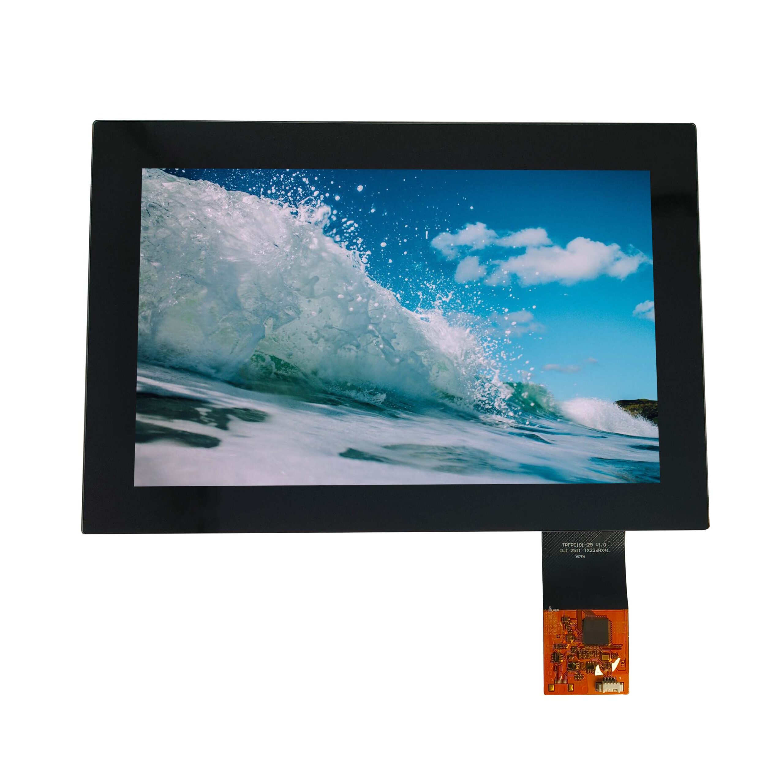
Capacitive touch in a vehicle fails in ways that never appear on a bench: a phantom press when the wipers run, a dead zone under a gloved finger, a stuck column of pixels when rain sheets across the glass. All three come from the same source – a small capacitive signal measured in an electrically hostile place – and all three are addressed through grounding, tuning and material choices made before the first sample.
Part of the Vehicle LCD Displays guide — 23 articles on specifying, replacing and qualifying automotive TFT modules.
How the automotive EMC environment attacks a capacitive sensor
It couples noise into the sensor as a false signal.
A capacitive sensor works by measuring femtofarad-scale changes in coupling, and any nearby electric field can add to that measurement. In a vehicle the aggressors are everywhere: motor drives, LED lighting, DC-DC converters, ignition systems, wireless transmitters and the display’s own backlight driver. The sensor’s countermeasures are differential sensing, frequency hopping away from interfering bands, and a physical stack that keeps aggressor current out of the sensor loop.
The failure modes are asymmetric. Some appear as lost sensitivity – touches that do not register – and others as phantom touches that register with no finger present. Design reviews should look for both, because a fix that improves immunity often shifts the problem from one to the other. EOS/ESD Association material is a useful reference for the static-discharge side of the same problem, which reaches the sensor through the cover glass and the bezel.
CISPR 25 and ISO 11452 test setups that expose touch failures
Test the whole front assembly, powered, with a real host.
Component-level certificates do not predict touch behaviour in a vehicle. The relevant tests energise the assembly while the touch controller runs: radiated immunity sweeps, conducted transients on the supply, and injected noise on the touch and display cables. The parameters that matter during the run are baseline capacitance stability, reported touch coordinates and the number of false reports. A controller that recovers within a frame is acceptable; one that needs a reset is not.
Run the tests with the display at the brightness the vehicle will actually use, because backlight switching noise scales with drive current and the worst case is often at a mid-dimming point rather than at maximum. Record which firmware parameters were in force during the run, because immunity results are meaningless without the configuration that produced them. The test methods that automotive programmes reference for these runs are published through the SAE standards programme, and industry coverage of the underlying electronics is available from Semiconductor Engineering.
Grounding and shielding strategy for a bonded touch stack
Give the aggressor current a return path that avoids the sensor.
The two decisions that matter are where the display’s ground reference connects relative to the touch controller, and how the FPC and cable are routed and shielded. A bonded stack is electrically quieter than an air-gap stack because the layers are in intimate contact, but the bonding adhesive also changes the parasitic capacitance, so the controller must be tuned after assembly, not before.
Practical rules: keep the touch FPC away from the backlight and inverter paths; give the sensor a low-impedance reference to the host chassis at a single defined point; and avoid daisy-chaining display and touch grounds through a long thin conductor. Where a metal bezel or frame is used, its connection to the sensor reference is a design decision that should be documented, not left to assembly tolerance.
False touches from rain, spills and condensation
Water changes coupling, so the controller reads it as a finger.
A film of water on the cover glass couples sensor electrodes together and produces reports that look like a large, slow, moving touch. Rain arriving at speed is worse than a puddle because the pattern changes with every frame. Mitigations are algorithmic – rejecting slow-moving, low-contrast ghost patterns – and physical, such as hydrophobic surface treatments and avoiding large continuous electrode areas near the edges where water collects.
Condensation on the inside of the glass is the harder problem, because it appears after thermal cycling and it cannot be wiped. It is largely eliminated by bonding the display to the cover glass, which removes the air layer where moisture condenses; where bonding is not used, controlled venting and assembly in a low-humidity environment do the same job less completely.
Glove operation: what firmware tuning can and cannot fix
Tuning recovers thin gloves, not thick ones.
A glove adds a dielectric layer between the finger and the sensor, reducing the measured change. Increasing gain recovers thin leather and nitrile gloves, but it also increases susceptibility to noise, so there is a direct trade between glove sensitivity and EMC margin. Thick winter gloves, especially dry wool or rubber, may reduce coupling beyond what any gain setting can recover without unacceptable false-touch rates.
Decide the glove requirement early and in writing: material, thickness and whether the vehicle will be operated with gloves on for safety reasons. Where thick-glove operation is mandatory, the design answer is usually a different sensor pattern, a thinner cover glass in the touch area, or a hybrid interface with physical controls for primary functions. CDTech’s material on gloved hands and rain covers the tuning techniques and their limits.
Thick cover glass, optical bonding and sensitivity trade-offs
Every 0.5 mm of glass costs signal margin.
Cover glass thickness improves impact resistance and durability but reduces the capacitive coupling change a finger produces. Optical bonding helps by removing the air interface, which improves both optical performance and coupling consistency, but the adhesive itself becomes part of the dielectric stack. The practical design sequence is to fix the glass thickness from the impact requirement, then size the sensor pitch and controller gain to suit, then confirm with a grid test on a bonded sample.
ASTM D1003 defines the haze measurement that goes with any surface treatment choice, and haze affects perceived clarity as much as touch does. Glass suppliers such as AGC document the base material properties that feed into the stack calculation.
Baseline capacitance drift across temperature
Drift is normal; unexplained recalibration is not.
Baseline capacitance changes with temperature, humidity and mechanical stress, so every controller continuously retunes its reference. The failure is not drift itself but a controller that recalibrates while a finger or a water film is present, then loses the touch or treats the release as a new press. Controllers handle this with compensation windows, and the settings that define those windows are worth locking early.
Validate drift behaviour with the display at both temperature extremes, at night-time brightness and at full brightness, with and without a finger on the glass. That matrix catches most field-reported touch anomalies before they leave the lab.
Firmware parameters worth locking before PPAP
Freeze the settings that define feel and immunity.
The parameter set that should be version-controlled includes the sensor configuration, gain and threshold profiles, glove and water rejection thresholds, frequency-hopping scheme, calibration window settings, and the coordinate transformation for the specific glass geometry. Any of these changing after PPAP is a functional change and should trigger notification, because the customer’s integration validation assumed the frozen behaviour.
Record the settings with the firmware version in the PPAP submission and keep a golden sample with those settings programmed. When a field complaint arrives, comparing the unit’s settings with the golden configuration is the fastest way to separate a software drift from a hardware defect.
Debugging a false-touch complaint in the field
Reproduce the environment before changing firmware.
Start by capturing the conditions: vehicle state, weather, brightness setting, whether the seat heater or wipers were active, and the exact screen area affected. Then reproduce with the sensor raw data logged, because the reported coordinates rarely show the cause. False touches that correlate with the wiper motor point to a conducted path; those that correlate with rain point to surface coupling; those that appear only after the cabin heats up point to drift compensation.
Only after the mechanism is identified should the fix be chosen. Changing gain as a first response tends to trade one complaint for another.
Sample validation plan for an automotive touch programme
Validate the assembly, in the installed condition, at the extremes.
- Touch accuracy grid test on the bonded assembly, including the outer 10 mm, with and without gloves.
- Immunity runs at low, mid and full brightness, with raw data logging.
- Wet and rain simulation test at the specified water application rate.
- Thermal cycling with functional touch checks at each extreme.
- ESD discharge tests at the specified contact and air levels.
- Long-duration baseline drift log over at least one full temperature cycle.
Each item produces a record that supports the EMC and safety documentation the vehicle programme needs, including the internal electronics requirements referenced in IEC 62368-1 and the design targets set by the EU EMC Directive for equipment sold in Europe.
FAQ
Why does a car touchscreen stop working in the rain?
Water on the surface couples sensor electrodes together, which the controller interprets as a touch or as several simultaneous touches, often rejecting the whole frame as invalid. Hydrophobic surface treatment, edge electrode design and ghost-pattern rejection in firmware reduce the effect, but a fully soaked screen may still become unresponsive until it clears.
Can capacitive touch work with thick winter gloves?
Usually not without a design change. Increasing gain recovers thin gloves at the cost of noise margin, but thick dry gloves may reduce coupling below any usable threshold. Where thick-glove operation is mandatory, the practical answers are a thinner touch area, a different sensor pattern or physical controls for primary functions.
Does optical bonding improve touch performance or only optics?
Both. Bonding removes the air gap, which improves contrast and viewing angle and removes the surface where condensation forms, and it also makes the dielectric stack more consistent, which helps coupling uniformity. The adhesive becomes part of the electrical design, so tuning must be done on the bonded assembly.
When should touch firmware parameters be frozen?
Before PPAP, and then treated as a controlled characteristic. Gain, thresholds, rejection profiles, frequency hopping and coordinate transformation all change touch behaviour, so a post-approval change invalidates the validation the customer performed. Keep a golden sample programmed with the approved settings for field comparisons.
Next step
If a touch stack is failing immunity or glove tests, CDTech can review the sensor design, bonding method, cover glass thickness and controller tuning as one stack, and supply samples with the parameters documented.
Send the test conditions and current failure log to sales@cdtech-lcd.com, or start from the contact page.
Related articles
 Automotive Wide-Temperature Displays: Designing for -40 C to +85 C OperationVehicle & Automotive Displays
 Headrest and Rear-Seat Entertainment Displays: Choosing Between LCD, OLED and ProjectionVehicle & Automotive DisplaysHow to Manage LCD End-of-Life in Vehicle Programs Without Redesigning the ModuleVehicle & Automotive DisplaysHow to Qualify an Automotive LCD Display Supplier for an IATF 16949 ProgramVehicle & Automotive Displays