Automotive Wide-Temperature Displays: Designing for -40 C to +85 C Operation
Automotive wide-temperature displays from -40 C to +85 C: response time collapse, polarizer limits, cold-start backlight behaviour and auditable validation.
A wide-temperature claim is the easiest specification in a display datasheet to write and the hardest to audit. Two suppliers can both print -40 C to +85 C and deliver very different behaviour at the extremes, because the number describes a test condition rather than the mechanisms that fail there. This article covers what actually breaks, how it is tested, and what belongs in the purchase drawing so the claim can be checked after the fact.
Part of the Vehicle LCD Displays guide — 23 articles on specifying, replacing and qualifying automotive TFT modules.
What the -40 C to +85 C range really tests in a TFT module
It tests materials and start-up behaviour, not just the panel.
The low end of the range stresses the liquid crystal response, polarizer adhesion, adhesive glass transition and any plastic in the stack; the high end stresses polarizer durability, adhesive creep, backlight lifetime and connector retention. A module can pass storage at both extremes and still fail the operating requirement, because operation adds self-heating, voltage stress and repeated power cycling to the temperature exposure.
Read the specification for three separate statements: storage range, operating range, and the conditions for starting and for running. Many modules operate across a wide range but require a restricted start-up window, which matters when a vehicle is switched on at -30 C in a car park. CDTech builds wide-temperature display variants across its vehicle and industrial ranges, and its technical blog covers the practical limits of operation at -40 C and beyond.
Response time collapse at low temperature and how heaters change the design
Response time at -30 C can be several times the 25 C figure.
Liquid crystal viscosity rises sharply as temperature falls, so switching slows and the image smears or ghosts. For a cluster that must not look broken on a cold morning, the options are a heater layer, a lower-viscosity LC mixture, or an image design that tolerates slow transitions. Heaters add a power budget, a control loop and a new failure mode if the thermostat or the heater film is not qualified, so they are usually reserved for applications where start-up readability is genuinely critical.
The specification should state the maximum acceptable response time at the lowest operating temperature, not only at 25 C, and it should state how the panel reaches that temperature. Where a heater is used, its inrush current and warm-up time belong in the same drawing as the display, because they interact with power sequencing and inrush current in the host.
Polarizer, liquid crystal and adhesive limits
Polarizer and adhesive, not glass, set the practical ceiling.
Two pieces of polarizer film sandwich the glass, and both are polymers with temperature limits, moisture sensitivity and a defined adhesion performance. At the hot end, they can shrink, yellow or lift at the edge; at the cold end, adhesive can become brittle and lose peel strength during thermal cycling. Optical bonding adhesive adds a third polymer with its own glass transition temperature, and that transition often shows up as a change in optical behaviour rather than as an obvious defect.
Buyers should ask which polarizer grade and which bonding material are used, and require the supplier to state the temperature range of each material rather than of the assembly alone. Where a module is bonded, the interface between adhesive and glass is the failure site to watch in cycling tests, and it is visible as edge lift or haze before it becomes a functional failure.
Backlight behaviour in cold start and summer soak
LEDs start dim and finish hot; the driver decides which you see.
Backlight LEDs lose luminous output as they heat, so a display calibrated in a warm chamber looks brighter cold and dimmer after an hour in a sun-soaked dashboard. A constant-current driver with calibrated dimming compensates for this; a simple resistor or a fixed-duty driver does not. At the cold end, the driver and the LED forward voltage shift, which can cause start-up flicker or a brief over-current if the supply has no soft-start.
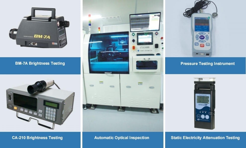
Test both extremes at the display, not at the power supply: measure luminance after cold soak, during warm-up, and at thermal equilibrium at maximum brightness. CDTech’s reliability programme includes aging and thermal testing of display modules, and the same parameters a buyer uses to check a claim – luminance, uniformity, colour shift – are the ones worth recording at each test point.
Thermal cycling vs thermal shock: which test exposes which failure
Cycling finds adhesion and connector fatigue; shock finds material mismatch.
Thermal cycling moves the assembly between two temperatures at a controlled rate over many cycles, which stresses interfaces that expand at different rates: polarizer edges, adhesive layers, gaskets, solder joints and connector contacts. Thermal shock moves between the extremes much faster and exposes materials that cannot tolerate the differential, such as some adhesives and glass-to-metal seals. Running only one of the two leaves a blind spot.
Chamber choice matters as much as the profile, and the equipment documentation from suppliers such as Weiss Technik or Thermotron is a reasonable reference for what a given chamber can actually hold at the specified transition rate. The test standard families that automotive programmes cite for environmental profiles are published through the SAE standards programme. Record the ramp rate, dwell time and cycle count in the report; without them the result is not comparable to another supplier’s data.
Where condensation forms in a sealed module
Condensation forms at the coldest surface inside the enclosure.
In a sealed module the coldest point during a cold start is usually the front glass, so moisture that entered during assembly or through a cable gland migrates there and appears as fogging between the display and the cover glass. An air gap is the classic site for this; optical bonding removes the air layer and the problem with it. Where the assembly cannot be bonded, a controlled vent path or desiccant is the alternative.
Design rules that help: assemble in a low-humidity environment, include a breathable membrane or a venting path where sealing is not absolute, and avoid trapping air between two sealed surfaces. Where IP sealing is claimed, the relevant definitions are in IEC 60529, and the sealing method should be stated in the drawing rather than implied by a single rating.
Validating a wide-temperature claim without a full chamber program
Three chamber runs plus an optical check cover most of the risk.
A reduced programme that still supports a claim typically includes a cold soak to the minimum operating temperature with functional and optical checks, a hot soak at maximum with brightness and colour measurements, and a cycling run that includes power cycling. Add a cold start from the minimum temperature with the backlight at maximum, because that single test exposes driver, heater and LC behaviour together.
Each measurement needs a defined instrument and a defined moment: luminance measured after a fixed dwell, uniformity measured on a fixed grid, response time measured with the same transition pair. Consistency matters more than sophistication, because the comparison that decides a supplier argument is the same test run on two samples.
Duty-cycle derating and lifetime impact
Every degree above the design point shortens backlight life.
LED lifetime is specified at a junction temperature, and operating a display at high brightness inside a sealed enclosure raises that temperature regardless of the ambient figure. The same module can therefore meet a ten-year target in a ventilated panel and miss it in a sun-soaked dash at the same measured ambient. Derating – running below maximum brightness in hot conditions, or shifting the brightness curve with temperature – is the standard mitigation and belongs in the display specification, not in the host firmware alone.
Ask for the lumen maintenance curve with its test conditions and the expected junction temperature in the application. A supplier that can reconcile the two has an engineering answer; one that quotes only hours at 25 C has a marketing answer.
What to specify in the purchase drawing so the claim is auditable
Name the conditions, the materials and the test method.
A purchase drawing that can survive an audit states the storage and operating temperature ranges separately, the cold-start condition, the maximum response time at the low temperature, the luminance at the high temperature with the measurement method, the polarizer and bonding material grade, the sealing method, and the environmental test profile with ramp rate and cycle count. It also states which of those parameters are checked on every production lot and which are type-test only.
Where the module includes a controller board, add the temperature range of every component on it and the safety standard the assembly is designed against, such as IEC 62368-1 for the internal electronics of information equipment. Adhesive material behaviour at the temperature extremes is documented by suppliers such as Henkel, and matching material data to the drawing is the fastest way to catch a substitution.
Supplier questions that separate a real automotive line from an industrial one
Ask what changes at the extremes, not whether the range is met.
Four questions do most of the work. Which material in the stack limits your high-temperature performance, and what is its rated temperature? What is the response time at the minimum operating temperature, measured how? Which test profile supports the cycling claim, including the ramp rate? And which parameters are 100 per cent inspected rather than sampled? A supplier with automotive experience answers with material names and test references; a supplier that buys panels and re-sells them answers with the datasheet.
Add a fifth question about change control: what notification would you issue if the polarizer or bonding material changed? If the answer is informal, the wide-temperature claim has no long-term protection, because the material is the claim.
FAQ
What happens to an LCD at -40 C?
The liquid crystal becomes viscous, so switching slows dramatically and the image ghosts or smears; polarizer and adhesive properties also change. Most modules need a heater, a low-temperature LC mixture or a start-up delay to be usable immediately at that temperature. Storage at -40 C is a different, easier requirement than operation.
Does a wide-temperature display always need a heater?
No. If the application only needs a readable screen after a warm-up period, or the vehicle cabin does not reach the specified minimum, a heater adds cost and a failure mode for no benefit. Specify the cold-start readability requirement first, then decide whether heating is the cheapest way to meet it.
How many thermal cycles are enough to qualify a display module?
The number should follow the mission profile and the standard your customer requires; programmes typically run between tens and several hundred cycles with defined ramp rates and dwell times. The count matters less than consistency: the same profile on the same fixture is what makes results comparable between suppliers and between revisions.
Can a display meet a temperature range without the controller board meeting it too?
No, and this is a common qualification gap. The panel may be rated well beyond the electronics that drive it, so the controller, connectors and any passive components must be checked against the same range. Ask for the assembly-level rating, not the panel-level rating.
Next step
Send the mission profile – ambient range, enclosure condition, cold-start requirement and duty cycle – and CDTech will return a wide-temperature module proposal with the material grades and test data behind the claim.
Write to sales@cdtech-lcd.com or use the contact page. Wide-temperature variants in the vehicle range are listed under vehicle LCD displays.
Related articles
 Headrest and Rear-Seat Entertainment Displays: Choosing Between LCD, OLED and ProjectionVehicle & Automotive Displays
 PCAP Touch Screens for Vehicles: EMI, Gloves, Water and Everything Else That Breaks ThemVehicle & Automotive DisplaysHow to Manage LCD End-of-Life in Vehicle Programs Without Redesigning the ModuleVehicle & Automotive DisplaysHow to Qualify an Automotive LCD Display Supplier for an IATF 16949 ProgramVehicle & Automotive Displays