EV Charger Display Design: Choosing a TFT and Touch Stack for Outdoor Charging Stations
EV charger display selection: brightness targets, -30 C to 70 C operation, gloved and wet touch, IP sealing, cable limits and the HMI spec to brief a supplier.
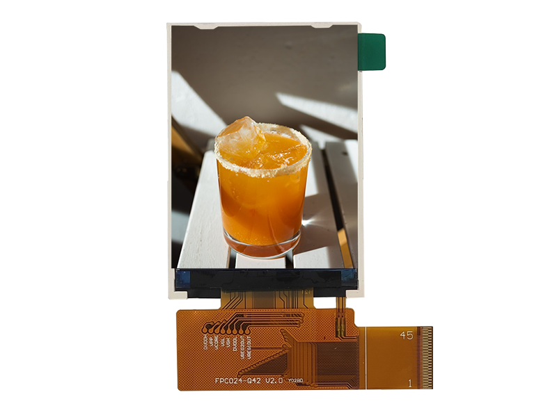
A charger HMI fails in the field for reasons that have little to do with the panel datasheet: rain on a capacitive layer, a gasket that hardens after two summers, an enclosure that reaches 70 C in direct sun, or a display cable that outgrew its interface. The specification work that prevents those failures happens before the first sample, and it is mostly about the enclosure, the light and the weather – not about resolution.
Part of the Vehicle LCD Displays guide — 23 articles on specifying, replacing and qualifying automotive TFT modules.
What do EV charger HMIs actually need from a display?
They need sunlight-readable, sealed, wide-temperature touch.
Charger panels do three jobs: identify the unit and its status, guide a driver through payment and connector handling, and satisfy regulatory labelling requirements. That means a display that stays legible in direct sunlight, survives an unheated curbside in winter, tolerates a sunscreen-smeared finger or a glove, and does not fog from the inside after a season of rain and morning sun. Contrast and sealing decide whether the unit feels reliable; resolution rarely does.
CDTech’s own technical scope for display and touch integration covers operating temperatures from -30 C to +85 C, surface treatments AG, AR and AF, and optical bonding with OCA and OCR. Those four items – temperature range, surface treatment, bonding and interface – are the core of a charger HMI specification. Everything else is a consequence of them.
Brightness and contrast targets for outdoor charging bays
Specify contrast in ambient light, not just nits.
Brightness figures are quoted in a dark room, which is the one place a charger never lives. What matters is how much reflected ambient light the front surface returns to the driver’s eye. A glossy cover glass can return more light than the panel emits, washing out the image no matter how bright the backlight is; an anti-glare surface treatment spreads the reflection and an anti-reflective coating reduces it, and both change the perceived contrast far more than another 200 nits.
A practical specification names the ambient condition – for example, direct sun on the panel face at midday – and the minimum contrast ratio acceptable in that condition, then verifies it on a bonded sample. CDTech publishes measurement guidance on measuring sunlight readability under real ambient light, which is the right way to settle a disagreement between a datasheet and a photograph. Bonded assemblies also lift perceived contrast because the air gap that would otherwise cause internal reflections is removed; the design trade-offs are covered in bonded versus air-gap displays.
Operating temperature: from -30 C winter curbside to 70 C enclosure heat
Design for the enclosure, not the weather forecast.
An outdoor pedestal in summer is a greenhouse: solar load plus backlight heat plus sealed air can push internal air well above the ambient temperature. In winter the same enclosure can sit below freezing for days, which affects liquid crystal response time and, if the unit is switched on cold, the power supply and backlight driver. Wide-temperature modules are specified exactly for this, and CDTech builds both wide-temperature and high-brightness variants across its display ranges.
The engineering task is to state the real internal air temperature at the display surface and the warm-up behaviour you need. If the charger must show a readable screen within seconds of a cold start, that is a different specification from a screen that is legible after two minutes. Add thermal cycling to the validation plan: repeated freeze-thaw with power cycling exposes gasket, adhesive and connector weaknesses that a single soak test never reveals.
Touch technology for gloved, wet and screen-protected charger fronts
Use PCAP with thick cover glass, then tune for gloves and water.
Projected capacitive touch is the default for public equipment because it is durable, sealed behind glass and supports multi-touch. The two failure modes to design against are water films on the surface and gloved fingers, both of which reduce the capacitive signal the controller sees. Controller tuning, sensor pitch and the thickness of the cover glass all interact: a thicker protective window raises durability but lowers sensitivity, so the glass, sensor and controller should be specified as one stack rather than three components.
Where drivers must work with heavy gloves, or the environment is consistently wet, a resistive touch panel remains a legitimate choice: it responds to pressure rather than capacitance, which makes it insensitive to water films and gloves, at the cost of optical clarity and multi-touch. CDTech manufactures both resistive and capacitive touch, so the decision can be made on the operating conditions rather than on what one factory happens to prefer. The practical test is a wet-glove test on a real sample at the specified glass thickness, not a catalogue claim.
IP and IK ratings: sealing the display into an outdoor pedestal
Seal the assembly, and specify the rating at assembly level.
A display module is not waterproof on its own; the rating belongs to the finished front assembly, including gasket compression, cover glass bonding, cable glands and the joint between the bezel and the pedestal. IEC 60529 defines the IP code that buyers cite here, and it is worth reading the definitions before writing IP65 into a drawing, because the second digit distinguishes water jets from immersion and the test conditions are not interchangeable.
Two practical points. First, specify the sealing method – bonded cover glass with a continuous adhesive bead, a compressed gasket, or a sealed bezel – and the surface preparation that goes with it, because adhesion depends on it. Second, specify impact resistance separately: IK ratings cover mechanical abuse and are independent of water ingress. Most charger field damage is impact from a connector, a bicycle or a cleaning tool, not immersion.
Condensation, UV and long-term gasket aging
Design for moisture leaving the enclosure, not only staying out.
Even a sealed enclosure breathes through temperature cycling, and the failure that follows is fogging on the inside of the cover glass, which users read as a broken screen. Mitigations are a properly sized and placed vent or breathable membrane, a desiccant where the volume justifies it, and avoiding sealed air paths that allow warm moist air to reach a cold glass surface. Bonding the display to the cover glass removes the internal air layer entirely and eliminates the most common fogging site.
UV and heat age every polymer in the stack: gaskets harden and lose compression set, adhesives yellow, printed graphics fade, and UV-blocking inks on the glass degrade differently from the glass itself. Accelerated aging with UV exposure and thermal cycling, run on production-intent materials, is the only credible way to qualify a front assembly. Cheap gasket material and unverified adhesives typically pass the first test cycle and fail the third.
Interface and cable length between display and controller board
Choose the interface from the cable run, then the layout.
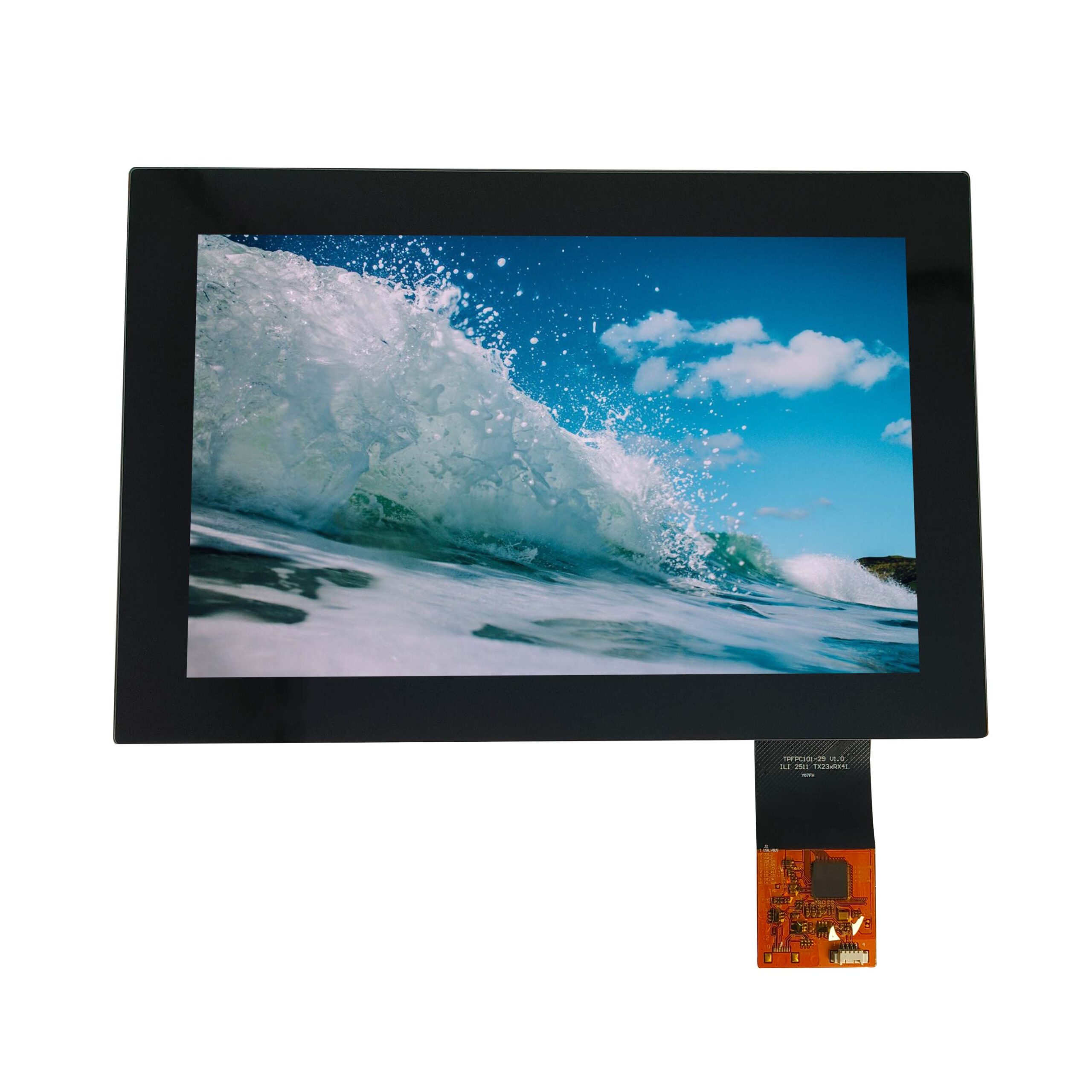
Inside a charger the display is often 200 mm to 800 mm from the main controller, routed near switching power supplies. Parallel RGB interfaces tolerate only short runs before skew and noise appear; LVDS, MIPI DSI and HDMI-class links carry the same image over longer distances with fewer conductors, and the trade is board cost and layout complexity. If the host already outputs HDMI or embedded DisplayPort, a display with a matching input and its own timing controller removes a whole conversion stage.
The choice should be made with the connector position, the bend radius and the shielding strategy in view, because a cable that works on a bench fails inside a pedestal with a 30 mm bend. CDTech supports RGB, MCU, SPI, MIPI, LVDS and HDMI across its display ranges, which means the interface can follow the system architecture instead of forcing a redesign late in the project.
Certification path: IEC 61851 enclosure, EMC and local utility requirements
Certify the system; select a display that does not obstruct it.
The charger as a whole is certified, not the display, so the display’s job is to make compliance easier: clean emissions, adequate immunity, no interference with the payment or RFID subsystems, and no surprise in the leakage-current budget if the front is touched while wet. IEC 61851 covers conductive charging systems and defines much of the enclosure and safety language that charger programmes use, while the EU EMC Directive and the CE marking framework set the European route to market.
Display-side measures that help most: a well-shielded or twisted cable with a short return path, backlight drivers that do not radiate across the band, and a touch controller with documented immunity behaviour. Safety requirements for the internal electronics frequently run through IEC 62368-1, and power architecture decisions made there – including the choice of an industrial supply such as those documented by MEAN WELL – affect noise and inrush in ways that show up on the display cable.
Reference specification table for 7-inch, 10.1-inch and 15-inch charger HMIs
Use a table like this as the brief, then let the supplier propose the stack. The values below are specification targets a buyer sets, not catalogue data: the supplier’s job is to state which combination is achievable and how it is verified.
| Parameter | 7-inch | 10.1-inch | 15-inch class |
|---|---|---|---|
| Primary role | Status, price, payment prompt | Full payment and session UI | Multi-bay or advertising panel |
| Brightness target | Sunlight-readable with AG or AR front | Sunlight-readable, bonded | High-brightness, bonded, glare-managed |
| Touch | PCAP, gloved and wet tuning | PCAP, gloved and wet tuning | PCAP, thicker cover glass |
| Operating range | Specify the internal air temperature at the display surface, not the local climate; state cold-start behaviour separately | ||
| Sealing | IP rating specified at the front assembly, with the sealing method and gasket material named | ||
| Interface | RGB, SPI or MIPI | LVDS, MIPI or HDMI | LVDS, eDP or HDMI |
| Validation | Thermal cycling with power cycling, UV aging, wet-glove touch test, impact test on the front | ||
How to brief a display supplier so the first sample is close
Send conditions, not adjectives.
A supplier can hit the target first time when the brief states the ambient light condition, the internal air temperature range, the required cold-start behaviour, the touch scenario including glove material and water, the sealing and impact ratings with the test references, the interface and cable length, and the mechanical envelope with connector position. Include a photo of the enclosure and the front glass drawing if one exists; the failures that matter most are mechanical, and a photograph removes more ambiguity than a paragraph.
Ask two questions in return: which parts of the stack the supplier recommends changing and why, and which tests will be run on the first samples. A supplier that answers both with specifics has understood the application. eeNews Europe covers the wider charger electronics landscape if you need context on how other subsystems in the pedestal are evolving alongside the HMI.
FAQ
Can a standard industrial TFT module be used in an outdoor EV charger?
Often yes, provided the front assembly, not just the module, is designed for the environment. The module must cover the internal temperature range with margin and be bonded or gasketed into a sealed front. The risk is not the panel itself but condensation, glare and touch behaviour under rain or gloves.
Is a resistive touch screen still acceptable for a public charger?
It is acceptable where drivers wear heavy gloves or the surface is frequently wet, because it responds to pressure and tolerates water films. The trade-offs are lower optical clarity, no multi-touch and mechanical wear, so most new charger designs use tuned capacitive touch instead.
How long should the display last in a charging pedestal?
Base the target on the charger’s service life and the daily duty cycle, and specify it as a backlight lifetime at a defined brightness and temperature. Ask the supplier to state the test conditions behind any lifetime figure, because a number quoted at room temperature is not comparable to one quoted at elevated enclosure temperature.
What is the most common EV charger display failure in the field?
Moisture and impact, in that order: internal fogging or water ingress on the front, and cracked cover glass from connector handling or cleaning. Both are solved at the assembly level with bonding, venting strategy, gasket specification and impact-rated front glass rather than by changing the panel.
Next step
Send the enclosure drawing, ambient conditions and touch scenario to CDTech and the first proposal will come back as a recommended stack – display, touch, bonding, cover glass and interface – with the tests that support it.
Contact sales@cdtech-lcd.com or use the contact page. Display classes used in outdoor equipment are listed under industrial LCD displays.
Related articles
 Automotive Wide-Temperature Displays: Designing for -40 C to +85 C OperationVehicle & Automotive Displays
 Headrest and Rear-Seat Entertainment Displays: Choosing Between LCD, OLED and ProjectionVehicle & Automotive DisplaysPCAP Touch Screens for Vehicles: EMI, Gloves, Water and Everything Else That Breaks ThemVehicle & Automotive DisplaysHow to Manage LCD End-of-Life in Vehicle Programs Without Redesigning the ModuleVehicle & Automotive Displays