How Can an MCU Drive a Small Bar TFT Screen Using SPI or I2C?
A small bar TFT can be driven directly from an MCU through SPI when its controller includes GRAM and accepts serial pixel writes. I2C is usually suitable for commands, touch, or monochrome displays—not full-color…
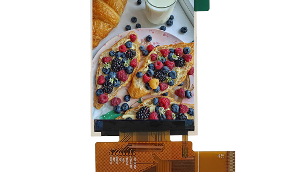
A small bar TFT can be driven directly from an MCU through SPI when its controller includes GRAM and accepts serial pixel writes. I2C is usually suitable for commands, touch, or monochrome displays—not full-color TFT frame updates. Select the interface from the required refresh rate, resolution, color depth, wiring length, and available MCU DMA resources.
server rack monitoring screen serialization protocol
What Do Competing Guides Commonly Cover?
Most articles about small displays focus on basic SPI wiring, I2C SDA/SCL connections, controller initialization, and simple drawing examples. Bar-type display pages also explain the physical benefit of an ultra-wide panel and distinguish SPI-only modules from SPI-plus-RGB panels.
The recurring questions are:
- What is SPI and how does it connect an MCU to a display?
- How does I2C display communication work?
- Which pins are required to connect an STM32 to a TFT?
- How do you initialize a TFT display controller?
- Why is SPI used for small embedded displays?
This article expands beyond basic wiring. It addresses the real constraints that determine whether a narrow TFT is responsive, whether a display can be updated without disturbing control loops, and why many “SPI displays” are only SPI-configured rather than SPI-rendered.
What Interface Should a Bar TFT Use?
Use 4-wire SPI for compact bar TFTs with internal display RAM, RGB or MIPI-DSI for larger high-refresh panels, and I2C mainly for touch controllers, OLEDs, character LCD expanders, or configuration functions. The deciding factor is not the connector pin count alone; it is the number of pixels that must move every second.
An embedded micro-controller screen does not require an RGB/LVDS interface if its display controller stores pixels internally. In that case, the MCU writes commands and image data into the controller’s GRAM through SPI.
For a small long-strip screen, this is often ideal. Examples include:
- Status bars for laboratory instruments.
- Battery or charging indicators.
- Smart-home control panels.
- Audio equipment level meters.
- Industrial process indicators.
- Compact automotive auxiliary displays.
- Narrow product information windows.
However, a panel described as “SPI + RGB” is not automatically an SPI-rendered TFT. In many cases, SPI only writes initialization registers, while the RGB interface continuously carries visible pixel data. This distinction is critical during component selection.
| Display architecture | Typical interface | Suitable use | Main limitation |
|---|---|---|---|
| Controller with internal GRAM | 4-wire SPI | Small bar TFT, icons, text, status UI | Full-screen refresh becomes slower as resolution rises |
| Controller with internal GRAM | QSPI / dual SPI | Faster compact HMI and animation | Requires compatible controller and MCU peripheral |
| RGB TTL panel | RGB565/RGB666 | Medium-to-large fast-changing UI | Consumes many GPIO pins and needs steady pixel timing |
| SPI initialization plus RGB pixels | 3-wire SPI + RGB | High-resolution bar TFT | SPI cannot normally carry full-frame content efficiently |
| I2C display module | I2C | OLED, character LCD, low-data indicators | Too slow for color TFT framebuffer updates |
For CDTech projects, the first question should be: “Does the selected panel have internal GRAM large enough to store the full active image?” If the answer is yes, SPI is normally practical. If not, an RGB, MIPI, external display controller, or video bridge solution may be required.
In our production discussions, the most expensive integration mistake is ordering a long bar panel because its specification says “SPI,” then discovering that SPI only initializes the ST7701S-class timing controller. The sample may power up correctly, but there is no practical serial path for continuous graphics. A schematic review before tooling avoids that failure.
How Does SPI Drive a Small Bar TFT?
SPI sends display commands and pixel bytes serially. The MCU controls chip select, identifies command versus data with a D/C pin, sends serial clock on SCK, and writes bytes through MOSI. A reset line provides reliable panel startup, while the backlight uses a fixed supply or PWM dimming signal.
A typical 4-wire SPI TFT connection looks like this:
STM32 MCU                     Bar TFT Module
---------                     --------------
3.3 V  ---------------------> VDD / IOVCC
GND    ---------------------> GND
PA5    SPI1_SCK ------------> SCL / SCK
PA7    SPI1_MOSI -----------> SDA / SDI
PA4    GPIO / SPI1_NSS -----> CS
PB0    GPIO ----------------> D/C or RS
PB1    GPIO ----------------> RESET
PA8    PWM GPIO ------------> BL / LED_EN
Optional MISO <------------- SDO (only if controller readback is required)
The practical minimum is usually six MCU outputs: SCK, MOSI, CS, D/C, RESET, and backlight control. MISO is optional because most production interfaces do not read display memory.
The SPI write sequence is typically:
- Pull CS low.
- Pull D/C low for a command.
- Transmit one command byte.
- Pull D/C high for command parameters or pixel data.
- Transmit one or more bytes.
- Pull CS high when the transaction is complete.
A normal full-screen write uses:
0x2A  Column address set
0x2B  Row address set
0x2C  Memory write
Pixel bytes in RGB565 format
For RGB565, every pixel uses 16 bits. A 160 × 80 bar TFT contains 12,800 pixels, so one complete framebuffer transfer requires:
160 \times 80 \times 2 = 25,600 \text{ bytes}At an effective 20 MHz SPI payload rate, that transfer takes roughly 10 ms before command overhead, software delays, DMA setup, and bus contention. A 20 fps full-screen refresh is realistic. A 60 fps full-screen animation is generally not.
The right engineering approach is to update dirty regions. If only a 20 × 40 numeric field changes, the MCU sends 1,600 bytes rather than 25,600 bytes. This is the difference between a responsive meter display and a visibly lagging screen.
Which STM32 Pins and Signals Are Needed?
An STM32 needs SPI clock, MOSI, chip select, data/command, reset, power, ground, and backlight control. SPI1 on many STM32 parts can use PA5 for SCK and PA7 for MOSI, but the exact alternate-function mapping must be verified against the specific MCU package and board layout.
A safe pin definition framework for a 3.3 V bar TFT is:
#define TFT_SPI_HANDLE        hspi1

#define TFT_CS_PORT           GPIOA
#define TFT_CS_PIN            GPIO_PIN_4

#define TFT_DC_PORT           GPIOB
#define TFT_DC_PIN            GPIO_PIN_0

#define TFT_RST_PORT          GPIOB
#define TFT_RST_PIN           GPIO_PIN_1

#define TFT_BL_PORT           GPIOA
#define TFT_BL_PIN            GPIO_PIN_8
The basic control macros should keep application code clear:
#define TFT_CS_LOW()    HAL_GPIO_WritePin(TFT_CS_PORT, TFT_CS_PIN, GPIO_PIN_RESET)
#define TFT_CS_HIGH()   HAL_GPIO_WritePin(TFT_CS_PORT, TFT_CS_PIN, GPIO_PIN_SET)

#define TFT_DC_CMD()    HAL_GPIO_WritePin(TFT_DC_PORT, TFT_DC_PIN, GPIO_PIN_RESET)
#define TFT_DC_DATA()   HAL_GPIO_WritePin(TFT_DC_PORT, TFT_DC_PIN, GPIO_PIN_SET)

#define TFT_RST_LOW()   HAL_GPIO_WritePin(TFT_RST_PORT, TFT_RST_PIN, GPIO_PIN_RESET)
#define TFT_RST_HIGH()  HAL_GPIO_WritePin(TFT_RST_PORT, TFT_RST_PIN, GPIO_PIN_SET)
Use 3.3 V logic unless the display module explicitly provides level shifting. A frequent field failure occurs when a 5 V development board drives an unprotected 3.3 V TFT input. It may function during bench testing, then develop intermittent display faults after electrical overstress.
For cable lengths below 100 mm, direct MCU-to-FPC-board signaling is usually manageable. Between 150 mm and 300 mm, we increasingly see clock-edge ringing at 24 MHz and above. A 22 Ω to 47 Ω series resistor placed close to the MCU SCK output often improves waveform quality. Do not place it at the display end; the source-end location controls the edge reflection more effectively.
CDTech normally recommends separating the LED backlight supply path from the display logic decoupling network. Backlight PWM current spikes can inject visible horizontal noise if LED return current shares a narrow ground segment with the panel’s analog supply return.
How Should STM32 SPI Initialization Be Structured?
Configure SPI as a master, full-duplex or transmit-only peripheral with 8-bit data frames, software-controlled chip select, a controller-compatible clock polarity and phase, and DMA for large pixel transfers. The panel controller datasheet—not a generic library—defines the required SPI mode and maximum clock rate.
A reliable low-level framework separates commands, parameter data, initialization tables, window setting, and pixel transfer:
static void TFT_WriteCommand(uint8_t cmd)
{
    TFT_CS_LOW();
    TFT_DC_CMD();
    HAL_SPI_Transmit(&TFT_SPI_HANDLE, &cmd, 1, HAL_MAX_DELAY);
    TFT_CS_HIGH();
}

static void TFT_WriteData(const uint8_t *data, uint16_t length)
{
    TFT_CS_LOW();
    TFT_DC_DATA();
    HAL_SPI_Transmit(&TFT_SPI_HANDLE, (uint8_t *)data, length, HAL_MAX_DELAY);
    TFT_CS_HIGH();
}

static void TFT_Reset(void)
{
    TFT_RST_LOW();
    HAL_Delay(10);
    TFT_RST_HIGH();
    HAL_Delay(120);
}

static void TFT_SetWindow(uint16_t x0, uint16_t y0,
                          uint16_t x1, uint16_t y1)
{
    uint8_t data[4];

    TFT_WriteCommand(0x2A);
    data[0] = x0 >> 8;
    data[1] = x0 & 0xFF;
    data[2] = x1 >> 8;
    data[3] = x1 & 0xFF;
    TFT_WriteData(data, 4);

    TFT_WriteCommand(0x2B);
    data[0] = y0 >> 8;
    data[1] = y0 & 0xFF;
    data[2] = y1 >> 8;
    data[3] = y1 & 0xFF;
    TFT_WriteData(data, 4);

    TFT_WriteCommand(0x2C);
}
The initialization sequence should never be copied blindly from a different panel, even if both displays appear to use the same controller family. Parameters such as frame rate, porch settings, gamma tables, VCOM, source-driver voltage, inversion mode, and scan direction may be panel-specific.
In factory bring-up, we often begin at 4 MHz SPI rather than the intended 24 MHz or 40 MHz. If the panel initializes consistently at low speed but fails at the final speed, the issue is usually signal integrity, clock phase, flex routing, or a marginal level-shifter—not the initialization commands themselves.
For full-region refresh, use DMA:
void TFT_WritePixelsDMA(uint8_t *pixelData, uint32_t length)
{
    TFT_CS_LOW();
    TFT_DC_DATA();
    HAL_SPI_Transmit_DMA(&TFT_SPI_HANDLE, pixelData, length);
}
The DMA-complete callback must release CS only after the final byte leaves the SPI shift register. Releasing it merely when DMA memory transfer completes can truncate the final pixel data on some STM32 configurations.
Why Is I2C Rarely Right for Color Bar TFTs?
I2C is rarely suitable for a color bar TFT because its practical payload bandwidth is far below SPI. It is excellent for display control, touch controllers, sensors, EEPROM devices, OLEDs, and character LCD adapters, but it cannot usually provide smooth full-color image updates.
At 400 kHz I2C, protocol overhead means the usable display payload is substantially below the clock rate. Even a tiny 160 × 80 RGB565 frame needs 25.6 KB. At 400 kHz, transferring one frame can take more than half a second in a real implementation.
Fast-mode Plus at 1 MHz improves the result, but it does not turn I2C into a graphics bus. It is still appropriate in these situations:
- A monochrome OLED showing small text or icons.
- An LCD module using an I2C GPIO expander.
- A TFT module with I2C touch plus SPI pixel data.
- A small secondary display that changes only once every few seconds.
- An intelligent display module that receives compact commands rather than raw pixels.
Do not confuse “I2C display” with “I2C TFT interface.” Many catalog modules market an I2C option because a touch controller, LCD backpack, or intelligent bridge board uses I2C. The TFT glass itself may still require SPI, RGB, MIPI-DSI, or another pixel interface.
For a low-pin embedded design, a highly practical architecture is SPI for the TFT, I2C for capacitive touch, and one PWM output for dimming. This uses seven to nine pins depending on reset, interrupt, and shared-bus choices while preserving adequate graphic performance.
Can a Small Bar Display Achieve Smooth Updates Over SPI?
Yes, if the panel is modest in resolution, SPI clocking is stable, DMA is used, and the firmware refreshes only changed areas. Full-frame animation works best on small GRAM-based displays; dashboards, counters, alarms, and segmented graphics are especially effective because they require partial updates.
Use this planning estimate:
\text{Maximum theoretical fps} =
\frac{\text{SPI payload bytes per second}}
{\text{horizontal pixels} \times \text{vertical pixels} \times 2}
A 160 × 80 display at 32 MHz SPI has an idealized ceiling near 156 full RGB565 frames per second. In real firmware, expect substantially less after command transfers, CPU activity, flash reads, DMA gaps, interrupt latency, and rendering time.
For practical design planning, use 50% to 65% of the theoretical transfer rate. That gives engineering margin and avoids starving other serial devices or real-time control tasks.
| Bar TFT resolution | RGB565 full frame | Practical SPI use case | Recommended strategy |
|---|---|---|---|
| 160 × 80 | 25.6 KB | Menus, meters, text, simple animation | Full-frame or dirty rectangles |
| 240 × 80 | 38.4 KB | Instrument labels, status pages | Prefer partial refresh |
| 240 × 320 | 153.6 KB | Portrait HMI | DMA plus region updates |
| 240 × 960 | 460.8 KB | High-detail bar dashboard | RGB interface, QSPI bridge, or intelligent controller |
With long bar displays, coordinate mapping can be more troublesome than bandwidth. A 240 × 960 glass may be physically mounted horizontally but logically organized as a portrait controller address space. The correct memory access control setting determines whether text is mirrored, rotated, or offset.
At CDTech, we advise creating a display abstraction layer before the UI is built. Include logical width, logical height, X offset, Y offset, rotation, color byte order, and panel-specific window rules in one configuration file. This avoids rewriting application graphics code after a mechanical orientation change.
Where Do SPI Bar-TFT Designs Usually Fail?
SPI bar-TFT designs usually fail at controller selection, power sequencing, coordinate offsets, backlight noise, non-DMA transfers, and incorrect initialization values. Most failures are avoidable when the display is treated as an electromechanical subsystem rather than simply another SPI peripheral.
The most common production-level issues are:
- The panel has no usable internal GRAM, despite having an SPI initialization port.
- The selected STM32 SPI prescaler exceeds the panel’s reliable signal margin.
- The firmware ignores RAM address offsets, leaving a persistent blank strip.
- Pixel color order is incorrect, turning red UI elements blue.
- The display is initialized before logic or analog rails are stable.
- Backlight PWM shares ground impedance with display power and creates flicker.
- The CPU blocks during pixel writes, delaying communication, control loops, or watchdog servicing.
- A generic ST7789 or ILI9341 initialization table is used on a panel-specific implementation.
A repeatable diagnostic sequence is more efficient than changing random register values:
- Confirm the correct supply voltages at the display connector during reset and backlight startup.
- Check reset pulse width and post-reset delay with an oscilloscope.
- Confirm SPI mode and examine SCK/MOSI edge quality at the display end.
- Transmit a solid red, green, blue, white, and black test sequence.
- Verify visible pixel dimensions and RAM offsets with a one-pixel border pattern.
- Increase SPI speed only after low-speed operation is repeatable.
- Enable DMA after the command sequence and static fills are stable.
CDTech Expert Views
“When customers ask for the lowest-pin-count bar display, we first separate physical pins from pixel bandwidth. A two-wire bus looks attractive on a schematic, but it cannot update a color TFT dashboard at the speed operators expect. In our production runs, a 160 × 80 RGB565 bar TFT over 24 MHz SPI is dependable for values, icons, alarms, and meter graphics when updates are limited to changed regions. For a 240 × 960 panel, SPI should normally initialize the controller while RGB or another high-throughput method carries the image. CDTech recommends approving the controller IC, GRAM architecture, FPC pinout, orientation, and backlight circuit together before locking the MCU board.”
When Should You Choose a Different Display Architecture?
Choose another architecture when the required display resolution, animation rate, video content, cable length, or user-interface complexity exceeds SPI’s practical bandwidth. A low-pin display is valuable only when its refresh performance remains suitable for the product’s actual operating conditions.
Move beyond direct SPI when:
- The panel needs 30 fps or higher full-screen animation at more than about 240 × 320 resolution.
- The interface must carry camera imagery, waveform motion, or video-like content.
- The display sits far from the MCU and needs more robust high-speed signaling.
- The user interface includes anti-aliased fonts, image blending, multiple gauges, and transition animation.
- The MCU cannot spare memory for a framebuffer, line buffer, or image assets.
- The application requires a high-resolution ultra-wide bar display.
Possible alternatives include:
- RGB TFT with an MCU LCD-TFT controller.
- MIPI-DSI display with an application processor or bridge IC.
- QSPI or serial display controller for moderate graphics throughput.
- HDMI display module for systems with an HDMI-capable host.
- Intelligent HMI module that accepts widgets, variables, or commands rather than raw pixels.
CDTech can help match the controller architecture to the actual content model. A thermostat-like narrow display, for example, may be excellent on SPI. A 960-pixel-wide animated production dashboard needs a different transport method even if its enclosure opening is physically narrow.
What Are the Key Takeaways for MCU Bar Screens?
A small bar TFT is easy to integrate with an MCU when it has internal GRAM, a genuine SPI pixel-write mode, and a resolution aligned with the required refresh rate. Use SPI with DMA for color bar displays, use I2C for low-data control functions, and verify the panel architecture before committing to hardware.
Take these actions before finalizing your design:
- Confirm whether SPI transfers pixels or only initializes the panel.
- Calculate RGB565 frame size before selecting the display interface.
- Use 4-wire SPI, D/C, reset, chip select, and PWM backlight control for a dependable compact design.
- Start at low SPI speed and validate signals before raising the clock.
- Build partial-refresh capability into firmware from the start.
- Use panel-specific initialization values and coordinate offsets.
- Choose RGB, QSPI, HDMI, or an intelligent module when high-resolution full-screen motion is required.
FAQs
Can STM32 directly drive a SPI bar TFT display?
Yes. An STM32 can directly drive a GRAM-equipped SPI bar TFT using SCK, MOSI, CS, D/C, reset, power, ground, and optional PWM backlight pins. DMA is recommended for pixel data so display updates do not block time-sensitive firmware.
Can I2C drive a full-color TFT display?
Usually not effectively. I2C is too bandwidth-limited for responsive RGB565 full-frame updates. It is better for OLEDs, character displays, touch controllers, simple indicators, and configuration interfaces.
What SPI speed should I use for a bar TFT?
Begin validation at 4 MHz to 8 MHz. After confirming correct initialization and waveform integrity, increase to 16 MHz, 24 MHz, or the panel’s verified maximum. Many compact TFT applications perform well between 16 MHz and 40 MHz with DMA.
Why does my SPI bar display show a blank edge?
The visible glass area may begin at a non-zero controller RAM address. Set the correct X and Y offsets in the column and row address commands, and verify rotation settings with a colored one-pixel border test.
Does every display labeled SPI support SPI graphics?
No. Some panels use SPI only for initialization and require RGB, MIPI, or another high-speed interface for image data. Always check whether the controller contains display RAM and supports serial memory-write commands.