Driving Unusual Resolutions: Custom Timing, EDID and Scaler Configuration
Driving unusual resolutions: custom timing entries, EDID behaviour, scaler or direct drive, colour depth limits and debugging out-of-range errors.
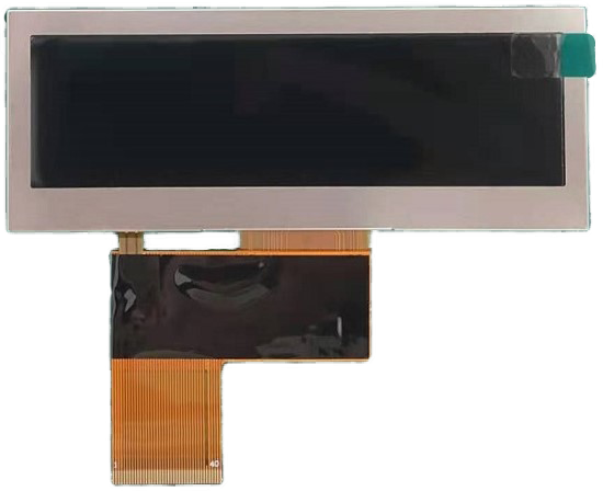
Bar displays, stretched formats and portrait panels all break the assumption that a display will present a standard video mode. The host asks for 1920×1080, the panel wants 1920×360, and the result is either no image or a stretched one. Fixing this is a configuration problem with a defined workflow, and the earlier it is planned the cheaper it is.
Part of the Interfaces, Touch & Signal Integrity guide — 39 articles on RGB, SPI, LVDS, MIPI, eDP and the touch controller.
Why bar and stretched panels break standard timings
Video standards describe aspect ratios the panel does not have.
Standard video modes come with fixed horizontal and vertical totals, blanking intervals and refresh rates. A bar panel with a 1920×360 array has a horizontal resolution matching a full-HD panel and a vertical resolution closer to a character display, so no standard mode maps onto it. Feeding a standard mode to such a panel produces either a lost image, a partial image or a scaled one, depending on where the scaling is done. The panel’s own timing table is the document that resolves this.
Obtaining the timing table early – with pixel clock, front and back porch, sync widths and polarities – is the single most useful thing a buyer can request from a display supplier. CDTech’s notes on display timing parameters explain each field in practical terms.
Pixel clock, blanking and sync polarity in practice
These four numbers describe the whole video signal.
The pixel clock sets the rate at which pixels are transmitted; the total horizontal and vertical counts include the active area plus blanking; the porches define where sync pulses sit within the blanking; and the sync polarity tells the panel where the active period begins. Getting any of them wrong produces characteristic symptoms – a shifted image, a rolling picture, a black border or no signal at all – which is why a timing table is more useful than a resolution figure.
Where the host’s output is configurable, the timing table can be entered directly. Where it is not, a bridge or scaler that accepts a standard mode and generates the panel’s timing is required.
EDID: what it declares and where it fails
EDID tells the host what the display can accept.
An EDID block lists the display’s supported modes, its preferred timing, and information such as the manufacturer and physical size. A host reads it and configures its output accordingly. Failures occur when the EDID does not include a mode the host insists on, when a non-standard timing is not expressible in the standard mode list, or when the EDID is corrupted or unreadable so the host falls back to a default that the panel cannot display. Emulating a known-good EDID is a common way to make a host behave, with the timing conversion handled downstream.
For custom formats, the practical route is often a controller board that presents a standard EDID to the host while generating the panel’s native timing, rather than trying to describe an unusual mode in an EDID that some hosts will ignore.
Scaler versus direct drive
One decision removes most of the difficulty.
| Approach | Advantages | Costs |
|---|---|---|
| Direct drive from the host | No extra board; lowest latency; simplest BOM | Host must generate native timing; changes if the panel changes |
| Controller with scaler | Accepts standard video; handles EDID and conversion | Adds cost, latency and another firmware element |
| Timing controller without scaling | Accepts native timing from a standard interface | Host must still output the correct timings |
Where the host’s output is fixed – a PC, a media player, a standard SoC – a scaler is the only practical route for an unusual format. Where the host is designed for the product, direct drive removes a board and a failure mode.
Writing a working custom timing entry
Start from the panel’s table, then verify each field.
- Enter the active resolution and the total horizontal and vertical counts.
- Set the front porch, back porch and sync widths from the panel data.
- Set the sync polarities as specified rather than by assumption.
- Choose the refresh rate within the panel’s supported range and matching the source content.
- Verify the pixel clock stays inside the interface’s capability at that refresh rate.
- Test at the extremes of temperature if the display operates across a range.
A timing entry that works at room temperature can fail at the extremes if the pixel clock is at the edge of the interface’s capability, so margin is worth leaving.
Rotating portrait panels without losing quality
Rotation is a scaling decision, not a mechanical one.
A portrait-mounted panel driven by a landscape-oriented host requires the image to be rotated. Doing it in the host costs processing but preserves quality; doing it in a scaler adds latency and, if the rotation is not an exact multiple of the panel’s pixel grid, softening. Where the content is text, rotation artefacts are visible; where it is a photograph, they are less so. The cleanest approach is to render the content in the correct orientation rather than rotate afterwards.
Mechanically, rotation also changes the viewing-angle behaviour and the polariser orientation, which affects how the display appears through polarised sunglasses and how colour shifts with angle.
Colour depth, subsampling and bandwidth limits
Colour depth consumes bandwidth quickly.
Increasing from 6-bit to 8-bit per colour raises the data rate by a third, and adding frame-rate or resolution increases it further. Where the interface is near its limit, the usual casualties are refresh rate or colour depth rather than resolution, and the symptoms are banding in gradients or a lower frame rate than expected. Subsampling schemes that reduce chroma resolution save bandwidth at the cost of colour detail in fine text and edges.
The calculation should be done once, at design time, with the panel’s native resolution and the required refresh rate, rather than discovered when the image banding appears.
Debugging out-of-range and no-signal problems
Four symptoms, four likely causes.
- No signal at all: check EDID reading, hot-plug detection and the host’s fallback mode.
- Image shifted or wrapped: check porches and sync polarity against the panel table.
- Rolling or unstable image: check the pixel clock and refresh rate against the panel’s range.
- Intermittent loss at temperature extremes: check timing margin and link training behaviour.
Logging the host’s detected mode alongside the panel’s required timing resolves most of these cases quickly, and it is worth building that diagnostic into the product during development.
Verifying timing stability over temperature
Timing margin is a thermal question.
The interface electronics and the panel’s own driver ICs change behaviour with temperature, and a link that runs at the edge of its margin when cold may fail when hot, or vice versa. Verifying the timing at the extremes – with the display running its worst-case content – is a short test that prevents a seasonal field problem. Where the link includes training (as eDP and some serial links do), the training result at temperature extremes is the parameter to record.
A simple check of captured frames or error counters at each extreme is usually enough to show whether margin exists.
Checklist for the display supplier’s timing table
Ask for these fields explicitly.
| Item | Purpose |
|---|---|
| Active resolution and scan direction | Confirms orientation and pixel grid |
| Pixel clock range | Sets the achievable refresh rate and margin |
| Horizontal and vertical totals with porches | Needed to build a working timing entry |
| Sync widths and polarities | Determines image position and stability |
| Supported refresh range | Prevents out-of-range operation |
| Interface data format and lane configuration | Matches the host output to the panel |
| EDID requirement and preferred timing | Determines whether emulation is needed |
| Behaviour on loss of signal | Defines the fail state for the product |
Interface specifications for these links are published by MIPI and HDMI.org, and practical timing and scaling behaviour is documented in component vendor material from TI and Analog Devices. CDTech’s notes on stretched versus standard panels cover the format side of the same problem.
FAQ
How can I create a custom EDID file?
Build it from the display’s supported modes and preferred timing, using the standard EDID structure, and verify that the host reads it and selects a workable mode. For formats that cannot be expressed as a standard mode, the more reliable approach is to present a standard EDID and convert the timing downstream.
Why does my display show out of range?
Usually because the host is sending a mode the panel cannot accept: an EDID that omits the panel’s native mode, a pixel clock outside the panel’s range, or a fallback mode chosen after an EDID read failure. Logging the detected mode alongside the required timing identifies the cause quickly.
Do I need a scaler for a bar display?
Only if the host cannot generate the panel’s native timing. Where the host is designed for the product, direct drive avoids the extra board and its latency. Where the host is a standard PC, media player or SoC with fixed outputs, a controller that accepts a standard mode is the practical route.
Why does the image band when I increase refresh rate?
Because the increasing data rate is being accommodated by reducing colour depth or by subsampling chroma when the interface is near its limit. Checking the bandwidth calculation against the interface’s capability, and choosing whether to reduce refresh rate, resolution or colour depth deliberately, avoids the symptom.
Next step
Send the panel resolution, host output, required refresh rate and EDID constraints to CDTech; the reply will provide the timing table, state whether emulation or scaling is required and identify the interface configuration.
Include the host output and required refresh rate in the enquiry to CDTech and the timing table will be returned with the interface configuration; write to sales@cdtech-lcd.com or use the contact page.
Related articles
 Bring-Up Debugging: No Display, Wrong Colours, Flicker and Everything in BetweenInterfaces, Touch & Signal Integrity
 Industrial Displays in High-EMI Environments: Protecting Signals and TouchInterfaces, Touch & Signal IntegrityFHD Versus IPS: Separating Resolution From Panel TechnologyInterfaces, Touch & Signal Integrity
 Integrating a Touch Sensor With a Display StackInterfaces, Touch & Signal Integrity