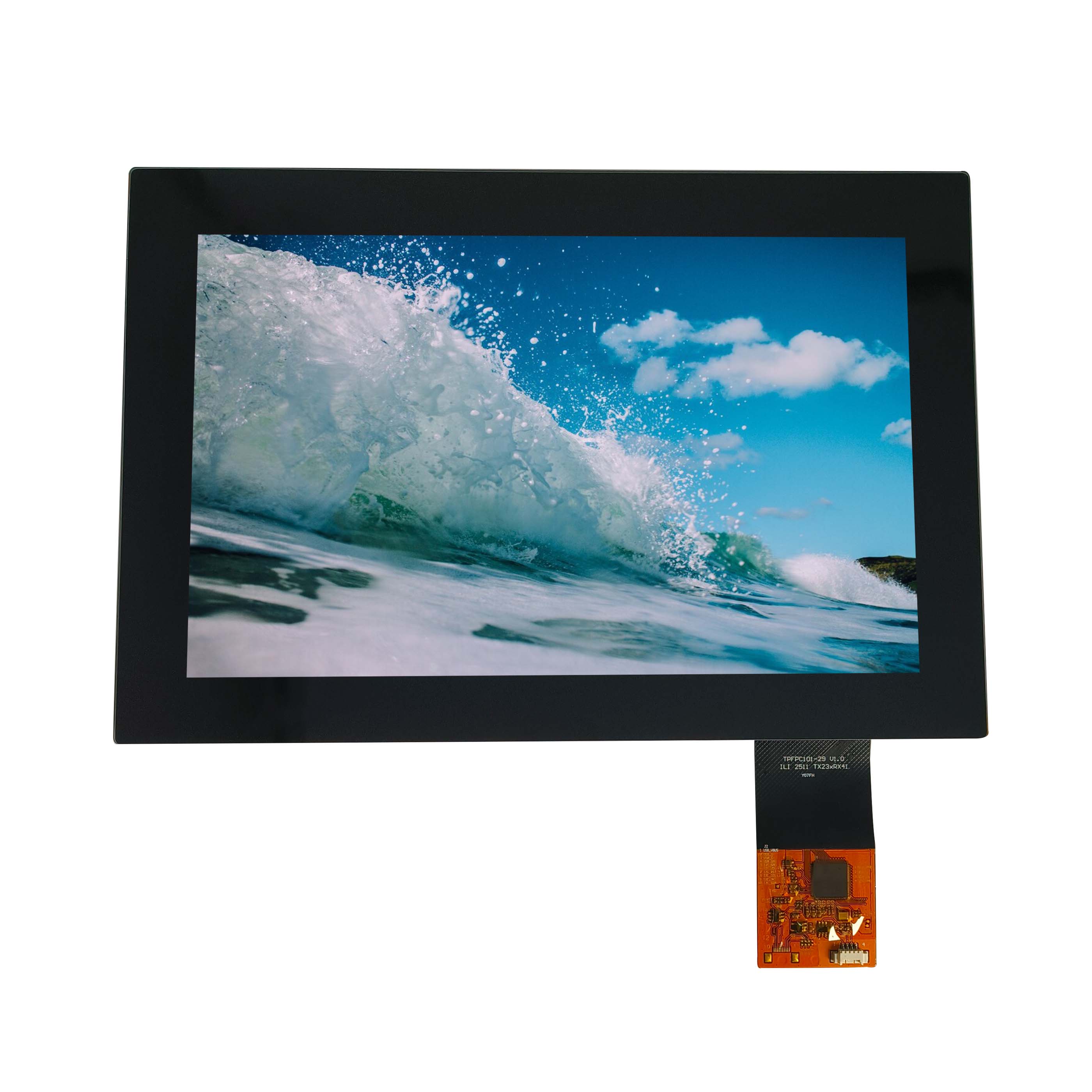
How Can WCG TFT Improve Medical Endoscope Imaging?
Wide Color Gamut TFT displays improve medical endoscope imaging by reproducing a broader and more controlled range of reds, greens, and intermediate tissue tones. By combining optimized LED spectra, quantum-dot films, matched color filters,…

Wide Color Gamut TFT displays improve medical endoscope imaging by reproducing a broader and more controlled range of reds, greens, and intermediate tissue tones. By combining optimized LED spectra, quantum-dot films, matched color filters, 10-bit processing, and factory calibration, a customized medical TFT can move beyond conventional 72% NTSC toward 95% NTSC or near-DCI-P3 performance while preserving clinically useful color differentiation.
What Makes Wide Color Gamut Important for Medical Endoscopes?
Wide Color Gamut matters in endoscopy because tissue interpretation often depends on small differences between reds, pinks, yellows, browns, and vascular tones. A conventional TFT may compress these shades into similar colors. A properly engineered high fidelity medical screen preserves more of the original camera information and produces smoother differentiation between adjacent tissue colors.
This distinction is important: a wider gamut is not valuable simply because it makes an image look more colorful.
For medical imaging, excessive saturation can actually be undesirable. The engineering objective is to expand the reproducible color space while maintaining predictable chromaticity, gamma, white balance, and grayscale behavior.
In practical display development, we often see conventional white-LED TFT modules designed around approximately 70–72% NTSC. They may be perfectly adequate for industrial HMIs, but an endoscopy system places much greater emphasis on red and green discrimination.
Consider a mucosal image containing pale pink tissue, a darker vascular network, and localized inflammatory redness. If the display’s red primary is spectrally broad or its color filter has excessive overlap, several subtly different camera values can produce visually similar output.
Increasing the usable gamut can create more separation between these colors.
The benefit is therefore not simply “more red.” It is more distinguishable red.
How Can a TFT LCD Reach 95% NTSC or DCI-P3?
A TFT LCD can approach 95% NTSC or DCI-P3 coverage by narrowing and repositioning its red, green, and blue spectral peaks. This normally requires changes to the backlight LEDs, optical films, quantum-dot conversion layer, color filters, or a combination of these components rather than simply increasing LED brightness.
The display color chain can be simplified as:
LED spectrum → optical conversion → color filter → liquid crystal cell → cover/touch stack → calibration → perceived image
Changing only one component rarely produces the best result.
For example, installing a higher-gamut LED package behind an existing LCD cell may increase measured saturation, but the existing color filter can still limit the final chromaticity coordinates.
Likewise, a quantum dot display film can generate narrower red and green spectral peaks, but its benefit is reduced if the LCD color filter transmission curves do not match those peaks efficiently.
A practical customization target may look like this:
| Display Configuration | Typical Gamut Target | Engineering Characteristics | Medical Application Fit |
|---|---|---|---|
| Standard white LED TFT | ~70–72% NTSC | Lowest complexity and cost | General medical UI |
| Enhanced-phosphor LED TFT | ~85–90% NTSC | Better red/green separation | Medical visualization |
| High-gamut LED + matched filters | ~90–95% NTSC | Better spectral control | Endoscopy |
| QD-enhanced TFT | 95%+ NTSC / near DCI-P3 | Narrower spectral peaks | High-fidelity endoscopy |
| Fully optimized WCG system | Application-specific | Gamut + gamma + calibration | Surgical imaging systems |
These figures should be treated as design targets rather than universal specifications. Actual performance depends on the LCD cell, backlight, optical stack, operating temperature, drive current, and measurement method.
At CDTech, we therefore treat gamut customization as a system-level optical project rather than a backlight-component substitution.
Why Does LED Spectrum Matter More Than Brightness?
LED spectrum determines where the TFT’s primary colors can land in color space, while brightness mainly determines luminance. Increasing a standard LED from 500 to 800 cd/m² can make an image brighter without materially improving its ability to separate closely spaced tissue colors. High-fidelity medical displays therefore require spectral engineering as well as luminance engineering.
This is one of the most common mistakes we encounter during display specification.
A customer may request:
“800-nit medical LCD with high color saturation.”
But 800 nits is not a color specification.
Two LCD modules can both measure 800 cd/m² while producing substantially different CIE coordinates.
For a conventional phosphor-converted white LED, the spectral energy distribution can be relatively broad. Once that light passes through the TFT’s RGB color filters, overlap between neighboring channels limits saturation.
A high-gamut backlight attempts to create better-separated spectral regions.
For medical endoscopy, the red-green relationship deserves particular attention. Vascular structures, mucosal surfaces, inflammation, and tissue boundaries can contain many neighboring chromatic values.
We have found during display tuning that simply pushing the red coordinate outward can make blood appear unnaturally vivid. The better approach is to tune the complete RGB balance and then verify intermediate colors rather than optimizing only the outer triangle on a gamut chart.
This is why CDTech evaluates both maximum gamut coverage and actual image behavior during customized medical TFT projects.
How Does Quantum Dot Film Improve a Medical TFT Display?
Quantum-dot film converts part of the blue LED output into narrow-band red and green light. Compared with conventional broad-spectrum phosphors, these narrower emission peaks can produce more saturated RGB primaries after passing through the LCD color filters, allowing TFT displays to achieve significantly wider color gamuts without replacing the LCD architecture with OLED.
A typical QD-enhanced backlight stack can be represented as:
Blue LEDs → light guide plate → quantum-dot conversion film → optical films → TFT LCD cell
The quantum-dot layer is particularly useful when the target moves beyond ordinary 72% NTSC performance.
However, integrating QD film into a medical TFT is not a drop-in exercise.
In our production evaluations, three issues receive particular attention.
First, optical efficiency.
Increasing gamut can reduce luminous efficiency because narrower spectral distributions and more selective filters may reject more light. A module that achieves excellent chromaticity but requires excessive LED current can create thermal and lifetime problems.
Second, spectral stability.
A medical device may operate for long sessions. As the backlight temperature rises, LED output and spectral characteristics can shift. Color measured immediately after startup is therefore not enough.
We normally want the design evaluated after thermal stabilization.
Third, material reliability.
The quantum-dot film sits inside an optical system exposed to heat and blue-light energy. Barrier performance and environmental stability matter. A laboratory prototype reaching a spectacular gamut measurement is irrelevant if the optical characteristics drift during product life.
For this reason, CDTech balances gamut, brightness, temperature, LED current, film stability, and service life rather than maximizing a single number.
What Does a CIE 1931 Diagram Reveal About Tissue Color?
A CIE 1931 chromaticity diagram shows the coordinates of a display’s red, green, and blue primaries and the color region enclosed by them. For endoscopy display development, comparing a standard TFT triangle with a customized WCG triangle helps engineers visualize how expanded red and green boundaries can preserve colors that would otherwise be compressed or clipped.
Imagine two triangles on the same CIE 1931 chart.
The smaller triangle represents a conventional 72% NTSC TFT.
The larger triangle represents the customized high-gamut backlight and panel combination.
The engineering value is not merely the extra area of the larger triangle. What matters is where that additional area appears.
For endoscopic imaging, extending the usable region around relevant red, orange, yellow, and green coordinates can be more meaningful than achieving a theoretically impressive expansion in colors rarely present in the medical video source.
This is where display customization becomes application-specific.
During a development project, CDTech can evaluate:
- RGB chromaticity coordinates
- white-point position
- gamut coverage
- color temperature
- luminance uniformity
- gamma response
- spectral power distribution
- color variation between samples
For a useful engineering comparison, I would plot the original panel, modified backlight prototype, and final calibrated module on the same CIE 1931 chart.
That immediately reveals whether the customization genuinely expands the intended color region or merely shifts the entire color balance.
Why Can 10-Bit Processing Matter as Much as Wider Gamut?
A wide gamut defines how far a display can reproduce colors, while bit depth determines how finely that space can be divided. A medical display with excellent gamut but insufficient color gradation can still show banding in smooth tissue transitions. A 10-bit pipeline provides up to 1.07 billion RGB combinations compared with approximately 16.7 million for conventional 8-bit processing.
This becomes important when displaying gradual changes across tissue surfaces.
A useful analogy is to imagine expanding a map without adding more coordinate points. The territory becomes larger, but the steps between available positions also become larger.
That is why wide gamut and high bit depth should be considered together.
| Parameter | Conventional Configuration | High-Fidelity Medical Target | Main Visual Effect |
| Color gamut | ~72% NTSC | ~95% NTSC / DCI-P3-class target | Broader color reproduction |
| Processing depth | 8-bit | 10-bit where pipeline supports it | Smoother gradients |
| White point | General factory setting | Application-calibrated | More predictable neutral tones |
| Gamma | Standard preset | Source/application matched | Better tonal separation |
| Backlight | Standard white LED | Spectrally optimized LED/QD | Improved RGB purity |
| Calibration | Generic | Module/system-specific | Better unit consistency |
There is another important qualification: installing a nominally 10-bit panel does not automatically create a 10-bit medical imaging chain.
The camera, image processor, interface, timing controller, panel driver, and display pipeline must preserve the required data depth.
If an upstream processor sends only 8-bit video, the display cannot recover missing gradations.
We therefore recommend verifying the complete signal path before paying the cost premium for a higher-bit-depth panel.
How Should a WCG Medical TFT Be Calibrated for Production?
A WCG medical TFT should be calibrated after the optical stack is finalized and thermally stabilized. Engineers should measure white point, RGB chromaticity, gamma, luminance, gamut, and unit-to-unit variation using production-representative modules. Calibration should correct repeatable deviations without attempting to compensate for unstable LEDs, poorly matched films, or excessive component variation.
This production stage is where many attractive prototypes fail.
One engineering sample can be manually tuned until it looks excellent. The real question is whether unit 500 or unit 5,000 behaves similarly.
Based on years of display manufacturing work, we pay close attention to binning.
LED wavelength and intensity variation can alter the final white point and gamut. Optical-film lots can introduce another layer of variation. TFT cell transmission also varies.
If tolerances are not defined during component selection, software calibration later becomes unnecessarily aggressive.
A better sequence is:
- Establish target chromaticity and luminance.
- Select compatible LED spectral bins.
- Match the optical film and TFT color-filter characteristics.
- Build pilot samples.
- Measure the warmed-up modules.
- Analyze unit-to-unit distribution.
- Define acceptable production limits.
- Apply calibration only after hardware variation is controlled.
This usually produces a more stable product than using firmware to rescue inconsistent optical hardware.
Medical projects should also test color after integrating the final cover lens or touch panel. Optical bonding materials, anti-reflection coatings, and protective glass can subtly change transmission characteristics.
The module should therefore be validated as the customer will actually use it.
What Engineering Trade-Offs Come With Wide Color Gamut TFTs?
Wide-gamut TFT customization can increase optical complexity, component cost, calibration requirements, thermal sensitivity, and supply-chain restrictions. The highest possible gamut is therefore not always the best specification. Medical equipment designers should select the smallest gamut expansion that reliably preserves required image colors while meeting brightness, lifetime, thermal, mechanical, and production-consistency requirements.
A 100% DCI-P3 target sounds better on a specification sheet than 95%.
But those final percentage points can become disproportionately expensive.
A tighter spectral requirement may reduce the available LED bins. A specialized QD film may increase procurement constraints. Higher backlight drive current may require thermal redesign. More demanding calibration tolerances may slow production testing.
There is also a fundamental brightness-versus-color trade-off.
Spectrally selective systems often sacrifice some luminous efficiency to obtain purer primaries. Compensating by increasing LED current generates additional heat.
More heat can accelerate LED degradation and alter optical characteristics.
This creates an engineering loop:
wider gamut → lower optical efficiency → higher LED drive → more heat → greater stability challenge
A competent customization program must break that loop through component selection and optical efficiency rather than simply applying more electrical power.
For an endoscope display, I would therefore prioritize stable, repeatable color over the last few percentage points of advertised gamut coverage.
CDTech Expert Views
“For medical endoscopy, we do not treat 95% NTSC as a marketing number. The first question is which tissue colors the imaging system needs to preserve. We then work backward through the LCD color filter, LED spectrum, optical films, signal depth, gamma, and calibration.
One lesson from practical TFT development is that the widest CIE triangle does not automatically produce the most useful medical image. Poorly controlled red saturation can make tissue look impressive but less natural, while inconsistent LED bins can cause visible differences between production units.
A better specification combines gamut coverage with RGB coordinates, white-point tolerance, luminance, gamma, thermal stability, and sample-to-sample variation. That converts ‘wide color gamut’ from a brochure feature into a controllable engineering requirement.”
How Should Medical Device Engineers Specify a Custom WCG TFT?
Medical device engineers should specify the complete visual target rather than requesting only a percentage of NTSC or DCI-P3. A useful RFQ should include display size, resolution, luminance, target gamut, RGB coordinates where required, bit depth, white point, gamma, viewing distance, interface, touch requirements, operating temperature, lifetime expectations, and calibration criteria.
The source camera should be part of that discussion.
If the endoscope processor outputs a particular color space, gamma curve, HDR format, or proprietary enhancement mode, the TFT should be designed around that source.
Otherwise, the display can technically achieve a large gamut while reproducing the incoming video incorrectly.
For an engineering RFQ, provide at least:
Display requirements: diagonal size, active area, resolution, viewing direction, brightness, contrast, viewing angle, and interface.
Color requirements: target gamut, reference color space, white point, gamma, bit depth, and allowable chromaticity tolerance.
Optical requirements: cover glass, anti-reflection treatment, optical bonding, touch sensor, surface hardness, and ambient-light conditions.
Reliability requirements: operating/storage temperature, LED lifetime target, humidity exposure, and expected continuous operating time.
System information: endoscope camera output, video processor, interface format, frame rate, and mechanical envelope.
The more precisely these parameters are defined, the less development time is spent chasing subjective comments such as “make the red more vivid.”
What Are the Key Takeaways for High-Fidelity Endoscope Displays?
A high-fidelity medical TFT requires more than a wide-gamut panel. Effective endoscope display customization combines spectrally optimized LEDs or quantum-dot films, compatible TFT color filters, adequate bit depth, controlled gamma and white point, thermal stability, production calibration, and system-level verification against the actual camera source.
Moving from approximately 72% NTSC toward 95% NTSC or DCI-P3-class performance can substantially expand the reproducible color region, particularly when the optical design improves red and green primary purity.
But gamut percentage alone should never become the acceptance criterion.
For a new endoscope or surgical robot display, define the colors that matter, establish measurable CIE coordinates and tolerances, verify the complete signal chain, and test multiple production-representative modules after thermal stabilization.
That approach produces a display that does not merely look more colorful in a demonstration. It produces one whose color behavior can be engineered, measured, repeated, and maintained through production.
CDTech supports customized TFT LCD, touch display, optical stack, backlight, interface, and display integration projects for medical equipment. For demanding endoscopy applications, early collaboration between the imaging-system engineer and LCD manufacturer is usually the fastest route to balancing color gamut, brightness, reliability, and manufacturability.
What Are Common Questions About WCG Medical TFT Displays?
Is 95% NTSC enough for a medical endoscope display?
For many high-fidelity TFT applications, approximately 95% NTSC represents a substantial improvement over conventional 72% NTSC panels. However, the correct target depends on the camera source and required color space. RGB chromaticity, gamma, white point, bit depth, and calibration accuracy should be specified alongside the gamut percentage.
Does quantum-dot film automatically produce DCI-P3 color?
No. Quantum-dot film can generate narrower red and green spectral peaks, but final gamut depends on the QD spectrum, blue LED, LCD color filters, optical stack, and calibration. The complete module must be measured to confirm actual DCI-P3 coverage.
Is a wider color gamut always better for surgical imaging?
No. An unnecessarily wide or poorly calibrated gamut can exaggerate tissue colors. The goal is accurate and repeatable differentiation, not maximum saturation. Medical display development should match the TFT’s color behavior to the imaging system rather than simply maximizing the CIE gamut area.
Can an existing 72% NTSC TFT be customized to 95% NTSC?
Sometimes. Backlight redesign using enhanced-phosphor LEDs or quantum-dot technology may substantially expand gamut, but the existing TFT color filters can become the limiting factor. CDTech normally evaluates the LCD cell, backlight spectrum, optical stack, thermal behavior, and target coordinates before determining whether the existing panel architecture is suitable.
What should be tested before approving a WCG TFT for mass production?
Test gamut coverage, RGB chromaticity, white point, gamma, luminance, uniformity, bit-depth behavior, thermal drift, LED aging, optical-stack effects, and unit-to-unit consistency. Measurements should be performed on production-representative modules after warm-up rather than relying only on a hand-tuned engineering sample.