Touch Controller Selection and Tuning: Getting Sensitivity Right the First Time
Touch controller selection: see the signal headroom each glass thickness consumes, the parameters to lock before production, and the evidence to request.
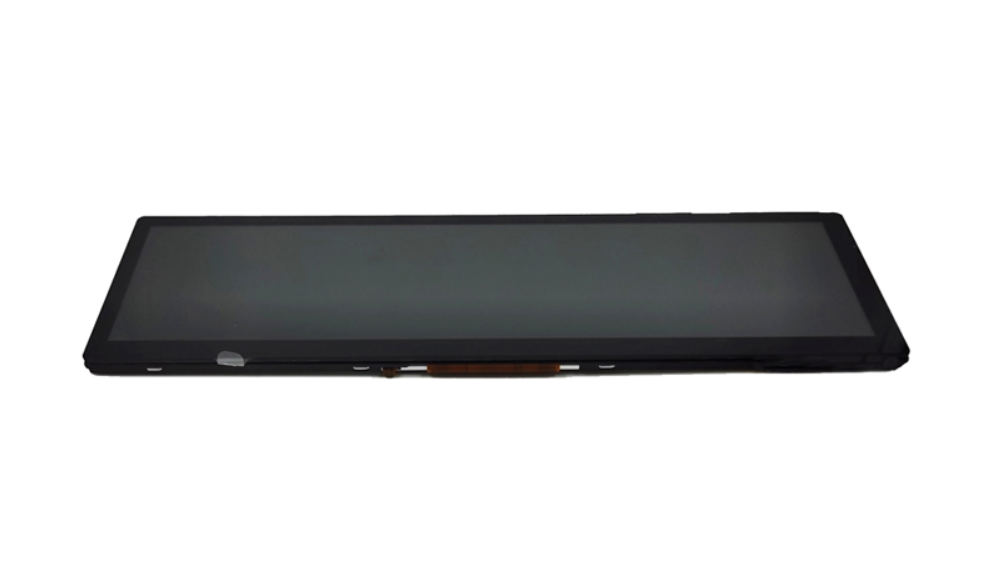
Most touch problems are decided before anyone writes firmware. If the controller lacks the channel count, the sensor pitch does not match the smallest expected touch, or the glass is thicker than the sensing margin allows, tuning can only trade one failure for another. Getting the selection right is what makes the tuning step short and predictable.
Part of the Custom Displays, Sourcing & Manufacturing guide — 46 articles on tooling, sampling, MOQ and supply-chain risk.
Last updated:
What a touch controller actually decides
It sets the signal budget the whole stack must live within.
The controller determines how many sensing channels can be read, how fast the sensor is scanned, how much noise rejection is available, how the baseline is tracked and how the touch coordinates are reported. Those capabilities bound what is achievable with a given sensor and glass. A controller with generous signal processing can tolerate a thicker cover glass or a noisier environment; one without cannot, regardless of how carefully its parameters are set.
The practical implication is that the controller, the sensor pattern and the glass thickness must be chosen together. Controllers intended for automotive and industrial touch, such as those documented by Synaptics and Goodix, are specified for the noise environments and glove conditions these applications need.
Channel count, node pitch and expected touch size
The sensor must resolve the smallest finger that will use it.
A capacitive sensor measures at the intersections of transmit and receive electrodes, so the pitch between electrodes sets the smallest touch that can be located accurately and the number of channels sets how finely the screen can be divided. If the pitch is large relative to the smallest expected finger – a child’s, or a gloved fingertip – accuracy and edge linearity suffer. Increasing the channel count improves resolution but raises cost, power and the complexity of the FPC.
The selection rule is to define the smallest touch to be supported and the accuracy required at the edges, then choose a pitch that resolves it with margin. Edge linearity deserves explicit attention because controls are often placed near the bezel.
Cover glass thickness and sensitivity headroom
Thickness consumes margin that cannot be recovered later.
Every additional millimetre of glass reduces the coupling change produced by a finger. Optical bonding helps by removing the air gap, which makes the dielectric stack more consistent, but it does not restore lost distance. The result is a sensitivity budget: thickness, adhesive, sensor layer and any protective film all consume part of it, and gloves consume more. Choosing a glass thickness without reference to that budget is how projects end up unable to meet their glove requirement.
Set the thickness from the mechanical requirement, then verify with a grid test on a bonded sample that the required input conditions – bare finger, gloved finger, wet surface – all fall inside the achievable range. CDTech’s cover glass guidance covers the mechanical side of the same trade.
Baseline tracking in temperature and humidity changes
Drift is normal; recalibrating at the wrong moment is not.
The controller continuously adjusts its reference capacitance as temperature, humidity and mechanical stress change. Problems arise when it recalibrates while a finger or a water film is present, because it then treats the touch as part of the baseline and loses contact, or registers the release as a new press. The parameters that govern this – compensation windows, update rates and thresholds – are the ones worth understanding, because their misconfiguration produces intermittent faults that are hard to reproduce.
Validate drift behaviour across the operating temperature range with and without a finger present, and at the brightness levels used in service, since backlight heat affects the panel and the sensor together.
Noise handling next to switching power supplies
The sensor hears the power supply before it hears the finger.
Capacitive sensing works in the femtofarad range, so switching noise from backlight drivers and DC-DC converters is significant. Controllers address it with frequency hopping, differential sensing and filtering, but the design must also help: keep the touch FPC away from the backlight path, provide a defined reference for the sensor, and avoid a ground arrangement that lets switching currents flow through the sensor’s return. Where the display is powered from the same rail as a motor drive or a large converter, the constraint is tighter.
The practical test is to run the noise aggressors at their worst-case operating point while logging raw touch data, rather than to judge performance by a finger tap on a bench. Static-discharge considerations for the same front surface are documented by the EOS/ESD Association.
Water rejection and palm rejection strategies
Two different problems with different signatures.
Water produces broad, slow, low-contrast coupling across several nodes and often at the edges, while a palm produces a large, high-contrast contact that is clearly a touch but should not be treated as a command in most interfaces. Controllers distinguish them through pattern analysis: rejecting signals that are too broad, too slow or inconsistent with a finger, and constraining expected touch sizes. The risk of over-aggressive rejection is that legitimate touches near the screen edge or with a gloved hand are also discarded.
Define the conditions to be tolerated – a wet finger, a water film, a resting palm – and test each explicitly, rather than tuning until the display seems satisfactory in one environment.
Glove mode trades and when it hurts bare-finger use
Increased gain buys gloves and costs noise margin.
Glove mode raises sensitivity so that a reduced coupling change is still detected. That also increases the chance of detecting noise, water films and unintended proximity, which is why a high-gain configuration can feel erratic with a bare finger. Where a product must serve both gloved and bare-finger use, the practical options are an adaptive profile that switches on a detected condition, a moderate fixed setting that covers the common case, or a design that reduces the glass thickness in the touch area.
Whichever route is taken, both conditions belong in the acceptance test, because a setting that satisfies one frequently degrades the other.
What Signal Headroom Does Each Glass Thickness Consume?
Thicker cover glass does not just reduce the signal, it consumes the controller’s headroom, and headroom is what pays for gloves, water films and a finger at the edge of a large cell. The table scales the sensed signal against a 2 mm reference to show how much margin is gone before any tuning starts.
Model with stated assumptions: treat the cover stack as a parallel-plate coupling path, so relative signal falls as 1/d against a 2 mm reference, with the adhesive, sensor pattern and controller gain held constant. Real modules recover part of the loss through a thinner adhesive layer, denser node pitch, or a sensor placed on the lens — but the trend is what decides whether tuning can succeed.
| Cover thickness | Relative signal (model, 2 mm = 1.00) | What it implies for the controller |
|---|---|---|
| 2 mm | 1.00 | Standard controller gain usually sufficient |
| 3 mm | 0.67 | Standard controller gain usually sufficient |
| 4 mm | 0.50 | Standard controller gain usually sufficient |
| 6 mm | 0.33 | Higher-gain or on-lens sensor needed |
| 8 mm | 0.25 | On-lens sensor plus high-gain controller; gloves and water become marginal |
Read the third column as a budget statement rather than a product recommendation. A controller tuned until it “just works” at the bench has spent its entire margin on the bare-finger case, so glove mode, a wet screen or a cold morning removes the last of it; that is the mechanism behind touch that passes in the lab and fails in the field. Locking the controller choice against the thickest stack the product will ship with is cheaper than retuning firmware per unit.
What to ask for as evidence. Request the controller’s specified sensitivity or signal-to-noise figure at the intended node pitch, the sensor construction and its measured capacitance, the tuning parameters shipped in production (gain, threshold, baseline tracking rate), and a test-grid result recorded at the extremes of the operating temperature range and with the input modes the product claims. A sample and quotation request is the fastest way to get a matched controller-sensor stack to test with.
Parameters worth locking before production
Six settings define the product’s touch behaviour.
- Sensor configuration and mapping for the specific glass geometry.
- Gain and detection thresholds, with the profiles used for each mode.
- Water and palm rejection thresholds and pattern rules.
- Baseline tracking rates and compensation windows.
- Frequency-hopping or scan scheme for noise avoidance.
- Coordinate transformation and edge linearity corrections.
Freeze these with the firmware version and keep a golden unit programmed accordingly, so that a field comparison is possible when a complaint arrives.
Test procedure for repeatable sensitivity evaluation
Turn the tuning result into a number.
- Define the input conditions: bare finger, each glove type, wet finger, palm rest, water film.
- Define a grid of test points including the outer 10 mm and the corners.
- Define the contact method: approach angle, pressure and dwell.
- Record the pass rate per point per condition with production firmware.
- Repeat at the temperature extremes and at the brightness settings used in service.
- Repeat with noise aggressors operating.
A test run this way produces a document that a customer can review and a design team can act on, and it takes a day per configuration. Related measurement practice appears in CDTech’s notes on touch screen calibration and on PCAP versus resistive touch.
When to change the controller instead of tuning it
Some problems are not parameter problems.
Change the controller when the signal is fundamentally too small – thick glass with gloves, for example – when the channel count cannot resolve the required touch size, when the required scan rate cannot be met with the chosen sensor, or when the noise environment exceeds the controller’s rejection capability. Each of those conditions can be identified from measurements rather than opinion: signal amplitude, noise floor, channel count and the required report rate.
Judging this early saves months. A stack that is marginal at the sample stage will not become robust in production, and the cost of changing a controller is small compared with the cost of a field campaign.
FAQ
How do I tune a capacitive touch screen?
Start from a controller and sensor with enough signal margin for the glass thickness and the input conditions, then set gain, thresholds, rejection profiles, baseline tracking and coordinate mapping against a defined test grid. Tuning allocates a signal budget; it cannot create one.
Why is my touch screen too sensitive?
Usually because gain and thresholds were raised to accommodate gloves or thick glass, which also amplifies noise and water-film signals. The answer is either an adaptive profile, a moderate fixed setting that covers the common case, or a design change that reduces the sensing distance.
Why does touch drift when the temperature changes?
Baseline capacitance changes with temperature, humidity and mechanical stress, so the controller retunes continuously. Failures occur when it recalibrates with a finger or water present, producing lost touches or phantom presses. Validate behaviour across the operating range with and without contact.
When should a touch controller be replaced rather than retuned?
When the measured signal is too small for the stack, the channel count cannot resolve the required touch size, the required report rate cannot be achieved, or the noise environment exceeds the controller’s rejection capability. Those are measurable conditions, and addressing them early is far cheaper than a field correction.
Next step
Send the cover glass thickness, glove and water conditions, noise environment and required accuracy to CDTech; the reply will propose a controller and sensor combination with the achievable tuning window and a test plan to verify it.
Contact sales@cdtech-lcd.com or use the contact page.
Related articles
 Fuel Dispenser and Forecourt Displays: Safety, Sunlight and Continuous UseCustom Displays, Sourcing & Manufacturing
 Landed Cost for Display Modules: Freight, Duty, Packaging and the True Unit PriceCustom Displays, Sourcing & Manufacturing
 How to Audit a Display Factory: An Evidence-Based ChecklistCustom Displays, Sourcing & Manufacturing
 TFT LCD vs OLED vs E-Paper for Industrial Products: A 2026 Decision FrameworkCustom Displays, Sourcing & Manufacturing