Integrating a Touch Sensor With a Display Stack
Integrating a touch sensor with a display: stack order, bonding choices, optical and mechanical consequences, grounding and how to validate the assembled front. | Target URL: https://blog.cdtech-lcd.com/touch-sensor-integration/
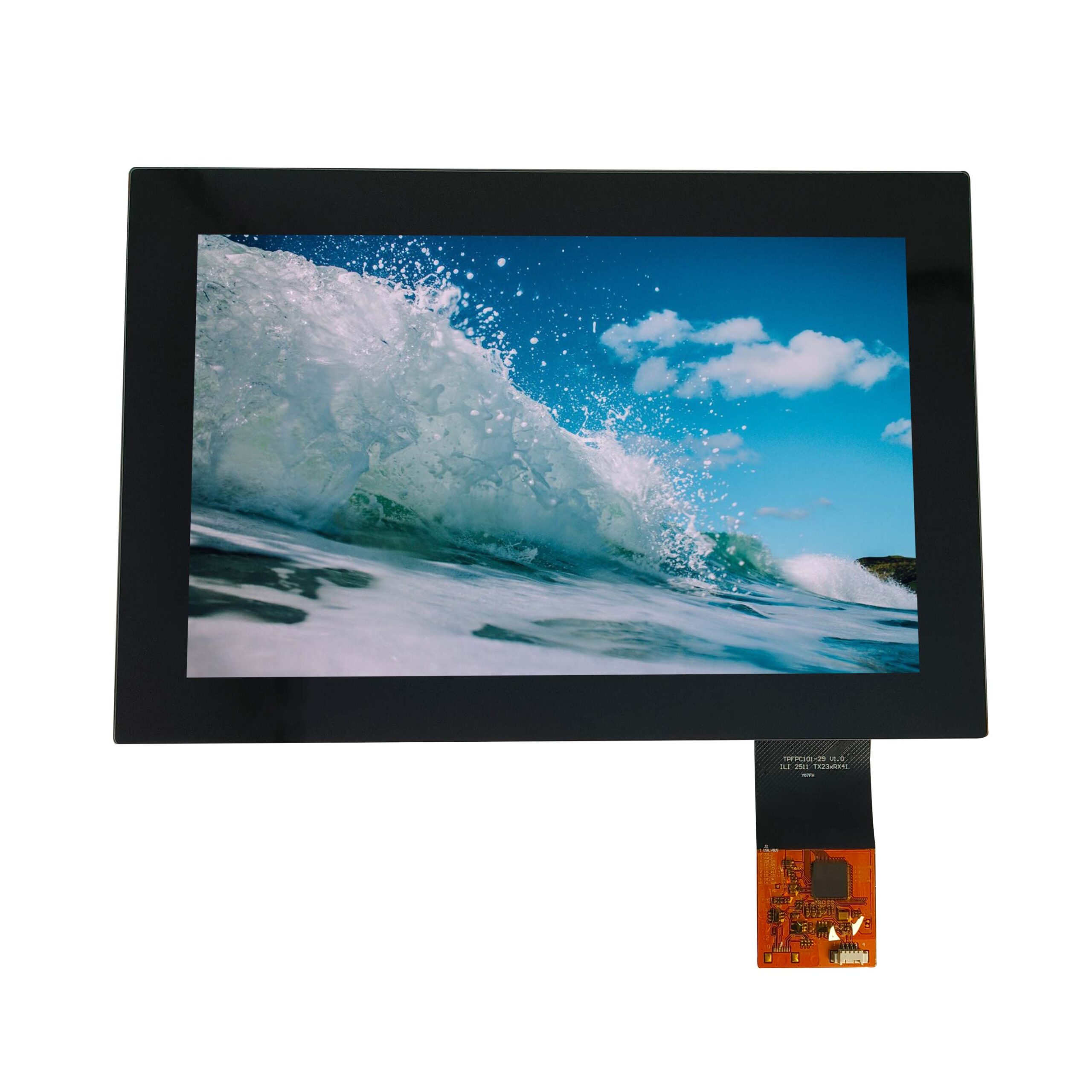
A touch panel and a display bought separately will not perform like a touch module, because what happens between them decides the result. The order of the layers, the adhesive, the gaps and the mounting path all change the brightness, the contrast, the touch baseline and the mechanical robustness. Most of those decisions are fixed the first time the parts are stacked, so the useful time to make them is before tooling.
Part of the Interfaces, Touch & Signal Integrity guide — 39 articles on RGB, SPI, LVDS, MIPI, eDP and the touch controller.
Which way round does the stack go?
Cover glass, sensor, bonding, display, in that order.
From the user inwards: the cover glass with its surface treatment, the touch sensor bonded to the glass or to the display, the adhesive or air gap, the display cell, and the backlight. Each interface in that list is a place where light is lost, a place where a gap can trap contamination, and a place where a mechanical load can concentrate. The single decision that changes most of the others is whether the sensor is laminated to the cover glass or to the display, and that is covered in the next section. The comparative view of the assembled options is in the display and touch solutions centre.
The layers and what each does
Five functions, each with an optical cost.
The cover glass protects and carries the surface finish. The sensor carries the electrodes and the routing to the tail. An adhesive layer removes the air gap and the reflections that come with it. The display cell sets the actual contrast and colour. The backlight supplies the luminance, and the light guide, diffusers and brightness-enhancement films determine the uniformity. Every transparent layer added between the backlight and the eye costs some transmitted light, and the losses compound rather than adding, which is why a bonded stack can be brighter than an air-gap stack with the same panel.
Sensor on the display or sensor on the cover glass
Two integrations, different mechanical stories.
Laminating the sensor to the display keeps the sensor in the touch controller’s preferred electrical environment and simplifies the cover glass, which can then be a plain sheet in a range of thicknesses. Laminating it to the cover glass produces a touch window that can be tested and stocked independently and replaced without discarding the display, which matters for a serviceable product. The trade is mechanical: a sensor on the front glass sits further from the display and may need a thicker front, while a sensor on the display needs the cover glass to be dimensionally stable enough not to load it.
Bonding methods for the stack
Air gap, adhesive sheet or dispensed resin.
An air gap is the cheapest and the worst optically, since it introduces two reflecting interfaces and a cavity that can collect dust. An optically clear adhesive sheet gives a controlled, uniform thickness and is well suited to flat, parallel surfaces. A dispensed optically clear resin conforms to curved or uneven surfaces and fills larger areas, at the cost of a more demanding process with a higher risk of bubbles and shrinkage. Materials suppliers publish the environmental and processing behaviour of these systems, and the adhesives from DELO and Henkel are documented in that form, as are the bonding tapes from tesa.
Optical consequences of each method
Contrast and haze are the visible results.
Removing the air gap raises contrast markedly and reduces internal reflections, which is the single largest optical gain available in a touch design. It also changes the measured haze and clarity, because the adhesive and the interfaces scatter a small amount of light; the measurement is defined by ASTM D1003 and applied to a finished cover glass in the treatment of haze, gloss and surface treatment. Bonding defects such as bubbles and mura are optical faults first and functional faults later, which is why inspection is part of the process rather than a final gate.
Thickness, weight and mechanical load
Every layer adds a lever arm.
A touch module is thicker and heavier than the display it contains, and the extra thickness increases the bending moment at the mountings whenever the front is pressed. The conventional answers are to support the glass near the edges, to avoid clamping through the active area, and to give the sensor tail a defined route that does not pass under a fixing. A stack that is well designed optically but poorly supported will show touch faults near the screws and, in the worst case, a glass crack at a boss. Cover glass suppliers such as AGC publish the strength and thickness data that the mechanical calculation needs.
Sealing, gaskets and the mounting path
Seal the glass, not the electronics.
For an ingress-protected product the gasket should act on the outer face of the cover glass or on a defined land, so that water never reaches the sensor or the display bond line. The mounting path then has to be independent of the sealing path, because a gasket that is also carrying the mechanical load will relax and leak. Bonded fronts tolerate cleaning and wipe-down far better than air-gap fronts, which is one of the reasons the bonded stack is standard in medical and food-industry equipment.
EMI, grounding and touch noise
The front has no shield, so the return has to be deliberate.
Because the cover glass carries no conductive layer by default, a discharge or a fast transient reaches the sensor directly, and the sensor’s own electrodes can couple noise into adjacent circuits. A continuous reference under the sensor, a controlled bond from the assembly to the chassis, and attention to the display drive frequency all reduce the disturbance, and where the product must survive discharges at the surface the practice published by the EOS/ESD Association applies. The controller firmware should be tuned in the final stack, including the actual cover glass and the actual housing.
Temperature and the touch baseline
Heat moves the baseline, and the firmware has to follow.
Capacitance changes with temperature, so a panel that is calibrated at room temperature will drift as the unit warms, and a backlight that dims changes the local thermal environment again. The controller’s drift compensation handles most of it, but only if it is allowed to run with the final firmware and the final thermal path. A stack validated with the backlight at full brightness and the lid open is not validated. The standard way to expose this is a soak at the extremes, with touch data logged rather than a pass or fail recorded.
Test and acceptance of the assembled front
Test the front, not the parts.
- Contrast and luminance measured with the sensor and cover glass fitted.
- Haze, gloss and colour of the finished surface against the target.
- An accuracy grid including the outer ring and corners.
- Recording with gloves, water and the cleaning agents in use.
- Drift and recovery across a thermal soak at both extremes.
- Discharge and mechanical tests on the assembled front.
Those six make a front verifiable rather than merely assembled, and they belong with the product’s quality assurance and factory compliance records. The manufacturing sequence that produces the front is described in custom touch panel manufacturing from sensor to module.
FAQ
What is a capacitive touch panel?
A transparent conductive sensor that measures the change in capacitance when a finger approaches, placed behind a cover glass. Nothing is pressed, so the surface can be sealed and gestures and multi-touch are possible.
Should the sensor be bonded to the display or to the cover glass?
Bond it to the display if you want the simplest cover glass and a shorter optical path; bond it to the cover glass if the touch front must be tested, stocked or replaced independently. The second option costs more thickness and weight.
Why does a touch display look duller once assembled?
Because each transparent layer between the backlight and the eye absorbs and reflects some light, and an air gap adds two reflecting interfaces. Bonding the stack with an optical adhesive usually recovers most of the loss, and improves contrast beyond the original figure.
How do I stop a touch panel losing accuracy near the edges?
Keep the bezel and any gasket from shielding the sensor, maintain a continuous ground reference under the edge channels, and include the outer ring explicitly in the acceptance grid. Retune the controller after the final cover glass is bonded.
Next step
Send the display outline, the cover glass, the touch requirement and the enclosure drawing to CDTech; the reply will state the stack order, the bonding method, the achievable contrast and the mounting scheme.
Contact sales@cdtech-lcd.com or use the contact page, or start from the sample and quote request page.
Related articles
 Bring-Up Debugging: No Display, Wrong Colours, Flicker and Everything in BetweenInterfaces, Touch & Signal IntegrityIndustrial Displays in High-EMI Environments: Protecting Signals and TouchInterfaces, Touch & Signal IntegrityFHD Versus IPS: Separating Resolution From Panel TechnologyInterfaces, Touch & Signal Integrity
 ZIF Connectors and Display ReliabilityInterfaces, Touch & Signal Integrity