OCA vs OCR Bonding: Which Is Better for Rugged Displays?
OCA and liquid OCR bonding both eliminate the air gap between a cover lens, touch sensor, and LCD, improving contrast, readability, and impact resistance. OCA suits repeatable flat-panel mass production, while liquid OCR better…

OCA and liquid OCR bonding both eliminate the air gap between a cover lens, touch sensor, and LCD, improving contrast, readability, and impact resistance. OCA suits repeatable flat-panel mass production, while liquid OCR better fills deep steps and complex curves. For rugged large-format displays, the winning process depends on geometry, bond-line control, curing uniformity, and long-term stress management.
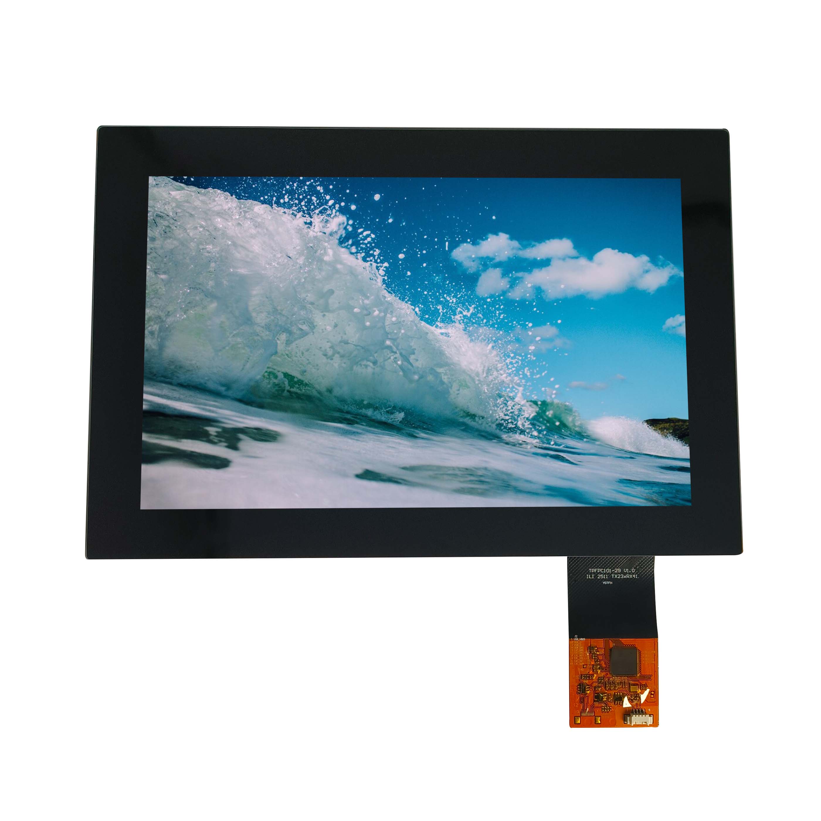
Touch screen with optical bonding
What Is the Difference Between OCA and Liquid OCR Bonding?
OCA is a pre-formed, pressure-sensitive optically clear adhesive film. OCR, also called LOCA in many applications, is a liquid optical resin dispensed between layers and cured by UV light, heat, or a combined process. OCA controls thickness through film selection; OCR controls thickness through dispensing volume, gap design, and assembly pressure.
Both methods remove the refractive-index discontinuity created by an air gap. That reduction in internal reflections improves perceived black level and outdoor readability, while the bonded stack better resists dust ingress, condensation, vibration, and cover-glass flex.
The manufacturing distinction is more important than the marketing distinction:
- OCA is a material-placement process.
- OCR is a fluid-management and curing process.
- OCA quality depends heavily on lamination pressure, alignment, surface energy, and bubble evacuation.
- OCR quality depends heavily on dispensing path, resin rheology, leveling time, UV dose, heat profile, and edge sealing.
In CDTech display projects, we do not choose the adhesive solely by display size. A 10.1-inch flat industrial display may run efficiently with OCA, while a narrow 28-inch bar-type display can become an OCR candidate because its long, flexible stack creates alignment and stress-control issues that a simple “flat panel” label does not reveal.
How Does OCA Perform in Industrial Mass Production?
OCA performs best when the display stack is flat, dimensionally stable, clean, and designed around a consistent bond-line thickness. Its main advantage is repeatability: each laminated unit begins with the same adhesive thickness, reducing variation caused by resin flow, dispensing volume, or incomplete UV exposure.
For standard industrial touch displays, OCA can support fast takt times because the film is die-cut or supplied in rolls, applied under controlled pressure, then finished through de-bubbling or autoclave processing. It is especially effective for thin cover glass, film-based touch sensors, and rectangular display geometries with well-controlled tolerances.
However, OCA is less forgiving when the gap changes across the panel. A film cannot naturally compensate for a raised bezel, a locally bowed LCD, a stepped touch sensor tail area, or a shallow curved cover lens. If the film is forced to bridge those variations, the result may look acceptable after lamination but later reveal edge lift, Newton-ring-like optical nonuniformity, or stress whitening.
| Production factor | OCA film bonding | Liquid OCR/LOCA bonding |
|---|---|---|
| Best geometry | Flat, stable, repeatable assemblies | Curved, stepped, irregular, or gap-variable assemblies |
| Bond-line control | Set by film thickness | Controlled by dispensing, gap and compression |
| Mass-production consistency | High after process stabilization | High only with strong dispensing and curing controls |
| Bubble risk | Trapped air at film placement or lamination | Air entrainment, voids, microbubbles during filling |
| Rework tolerance | Often limited; separation can damage polarizers | Possible before cure; difficult or impossible after cure |
| Typical factory challenge | Alignment and edge bubble control | Flow behavior, UV shadowing, cure shrinkage |
On high-volume flat products, OCA commonly gives a lower unit-to-unit variation. But this advantage disappears if panel flatness is poor. In production, an OCA film does not “correct” a warped cover lens; it records the mechanical mismatch inside the bonded stack.
Why Does Liquid OCR Suit Curved and Bar-Type Displays?
Liquid OCR suits curved and bar-type displays because it flows into variable gaps that solid adhesive film cannot reliably conform to. When correctly dispensed and cured, it can form a continuous optical layer across shallow curves, localized steps, narrow borders, and long aspect-ratio display stacks.
A 28-inch or 37-inch stretched LCD is not merely a larger version of a 10-inch panel. Its length magnifies glass bow, polarizer flatness variation, fixture deflection, and thermal expansion differences. On these displays, even a 0.2 mm height variation can create a visible flow pattern, a local pressure concentration, or a bubble channel if the process window is too narrow.
For a curved industrial control panel, OCR can be engineered with a bond line around 0.5 to 2.0 mm, depending on the curvature, bezel design, material stiffness, and shock requirement. That thickness gives the resin enough room to compensate for geometric variation. By comparison, very thin OCA films may be appropriate for a flat stack but cannot absorb a broad tolerance stack without transferring stress into the LCD.
In our production runs, we have seen long bar displays pass initial visual inspection and then develop corner lifting after thermal cycling because the fixture clamped the two ends more aggressively than the center. The adhesive itself was not the root cause. The root cause was unequal compression during assembly, followed by residual stress locked in during cure.
Liquid OCR is therefore not “better” by default. It is better when the product geometry requires the adhesive to act as an optical and mechanical gap-filling layer.
Which Process Delivers Higher Yield for Rugged Displays?
OCA usually delivers higher yield on flat, high-volume industrial displays with stable parts and narrow tolerances. Liquid OCR usually delivers higher yield on curved, oversized, stepped, or irregular assemblies because it accommodates geometry variation. The correct choice is the one with the wider validated process window, not the one with the lowest quoted material cost.
Yield should be measured beyond the first-pass cosmetic inspection. A production lot can show 98% immediate yield but fail after environmental testing due to residual stress, incomplete cure, or adhesive interface weakness. For rugged displays, meaningful yield should include optical inspection, electrical function, thermal cycling, humidity exposure, vibration, and edge-seal verification.
A practical selection approach is:
- Choose OCA when the bonded surfaces are flat, the gap requirement is thin, and panel-to-panel dimensional variation is tightly controlled.
- Choose OCR when the assembly includes curvature, significant height variation, a wide cover-lens border, or a long narrow panel susceptible to bending.
- Avoid using a thin OCA film as a low-cost substitute for a thick gap-filling resin.
- Avoid using liquid OCR merely because it can fill every gap; excess resin thickness can introduce cure shrinkage, optical distortion, and long-term yellowing risk.
CDTech evaluates display bonding as a stack-up problem. The cover glass, ink border, touch sensor, LCD top polarizer, gasket, enclosure clamp load, and operating temperature range all influence the final result.
How Can Factories Control Residual Stress After Bonding?
Factories control residual stress by managing adhesive thickness, lamination pressure, fixture flatness, resin shrinkage, cure rate, and thermal expansion mismatch. The goal is not maximum adhesion force; it is a balanced bond that remains stable when the display moves, heats, cools, vibrates, and absorbs impact.
Residual stress becomes dangerous when one layer is constrained while another layer continues to move. Glass, polycarbonate, acrylic, ITO touch films, LCD polarizers, and metal housings all expand differently. A bonded stack may remain flat at room temperature yet generate shear stress at 70°C or below freezing.
For large-format and curved assemblies, the following controls matter:
- Use a fixture with verified flatness across the entire active area, not only at its mounting points.
- Define compression limits with physical stops instead of relying on operator feel.
- Maintain controlled bond-line thickness across the center and edges.
- Reduce rapid UV curing that creates a hardened surface before the resin has fully leveled.
- Use gradual thermal post-cure when the resin supplier specifies it.
- Validate the finished module inside its actual housing, not only as an unmounted display stack.
A common hidden failure is enclosure-induced stress. A display may leave the bonding line perfectly flat, then become warped after screws or clips apply uneven force through the front bezel. CDTech therefore recommends reviewing optical bonding and mechanical enclosure design as one engineering package.
What Causes Yellowing During UV Curing?
Yellowing occurs when adhesive chemistry, UV exposure, heat history, contamination, or material incompatibility changes the resin’s optical transmission. It often appears as a warm tint near the edge, around the ink border, or in zones receiving excessive UV energy. Once visible yellowing occurs inside a cured bond, the display is generally physically scrapped.
UV curing is not simply a matter of applying more energy. Under-curing can leave residual reactive components, while over-curing can accelerate discoloration and increase resin brittleness. The correct dose depends on adhesive thickness, photoinitiator type, lamp spectrum, distance from the light source, exposure time, cover-glass transmission, and any black-mask or printed-border shadow area.
Factory prevention should include:
- Verify UV irradiance at the actual panel surface, not only at the lamp output.
- Monitor dose consistency across the full working width of the curing station.
- Match the adhesive’s photoinitiator response to the lamp wavelength.
- Prevent contamination from silicone oils, cleaning-agent residue, gloves, release liners, and poorly cured border ink.
- Control resin storage temperature, lot age, light exposure, and mixing procedure.
- Conduct accelerated aging checks on every material change, including a new ink, cover lens coating, or adhesive lot.
Yellowing can also be a compatibility issue. In one rugged-display scenario, a resin passed basic optical testing but changed color after prolonged high-temperature exposure because volatile compounds from a nearby foam gasket migrated toward the bond edge. The remedy was not a stronger UV dose; it was a compatible gasket material and improved edge isolation.
How Can Bubble Defects Be Prevented and Intercepted?
Bubble defects are prevented by controlling surface cleanliness, adhesive flow, dispensing pattern, vacuum level, lamination pressure, and de-bubbling time. They should be intercepted through staged inspection before cure, after cure, and after environmental stress. A bubble that survives curing becomes difficult to repair without damaging the display stack.
Not all bubbles are identical. A visible center bubble usually indicates poor lamination or insufficient resin coverage. A string of small edge bubbles may indicate trapped air escaping from a narrow gap. A delayed bubble that appears after thermal cycling often points to contamination, outgassing, or weak interface adhesion.
For OCR bonding, dispensing geometry is critical. The bead path must allow air to escape as the cover glass descends. If resin is dispensed as a poorly placed central pool, the advancing flow front can surround air and create void islands. For long bar displays, a controlled serpentine or segmented dispense pattern can reduce uneven flow, but only after the pattern has been validated for that resin viscosity and panel geometry.
For OCA, the main risk is often edge air caught during film placement or uneven roller pressure during lamination. A vacuum lamination sequence with sufficient dwell time helps evacuate trapped air, but excessive pressure can create local stress and distort thin films or touch layers.
Inspection should combine:
- Backlight-on visual inspection for bubbles and optical haze.
- Dark-field inspection for microvoids and edge channels.
- Polarized viewing when assessing stress-related distortion.
- Short thermal exposure before final packing to reveal delayed bubbles.
- Recordable acceptance criteria by location, size, quantity, and distance from the active area.
When Does Delamination Become a Physical Scrap Event?
Delamination becomes a physical scrap event when the adhesive separates from the cover lens, touch sensor, polarizer, or LCD surface and cannot be removed without damaging the optical stack. Edge lift may begin as a cosmetic issue, but it can become a pathway for moisture, dust, and progressive bond failure during vibration or thermal cycling.
The failure mechanism matters. Adhesive failure means the bond separates within the adhesive layer. Cohesive failure means the adhesive tears internally. Interface failure means the adhesive releases from one substrate. In rugged displays, interface failure is particularly serious because it often signals poor surface preparation, low surface energy, contamination, or chemical incompatibility.
The most common locations are:
- Corners, where peel stress concentrates.
- The boundary between black border ink and clear glass.
- Areas close to flex tails, raised components, or bezel transitions.
- Edges exposed to moisture or cleaning chemicals.
- Regions where the enclosure applies point loading.
To prevent scrap, identify early edge lift before the product reaches final assembly. Use controlled peel testing on representative coupons, cross-hatch or adhesion checks where appropriate, and environmental cycling on full stacks. A display that passes a room-temperature pull test can still fail in the field if the interface is not designed for heat, humidity, and mechanical cycling.
Can UV Curing Create Hidden Display Failures?
UV curing can create hidden failures when light exposure is nonuniform, resin is cured too quickly, shadowed regions remain under-cured, or heat generated during curing affects nearby materials. These defects may not appear immediately but can emerge as yellowing, haze, bubbles, brittleness, edge lift, or touch-performance changes after aging.
Large display modules present a particular challenge because UV intensity decreases with distance and can vary from the center to the edges. A curing recipe proven on a small touchscreen should never be copied directly to a 30-inch bar display. The lamp-to-panel distance, exposure overlap, conveyor speed, cooling interval, and panel orientation must be requalified.
Shadow zones are another concern. Black printed borders, opaque bezels, connector areas, and thick cover-lens features can block UV energy. If the resin under those areas relies on light alone, incomplete polymerization may remain trapped near the edge. A dual-cure adhesive system—UV plus thermal or moisture-assisted secondary cure—may provide a more robust solution for complex designs.
At CDTech, process validation should include cure mapping across the panel. This means confirming that every relevant location receives the intended energy and that the completed stack remains optically stable after high-temperature and humidity testing.
What Should Buyers Specify Before Releasing a Bonded Display?
Buyers should specify the display geometry, cover-lens material, thickness, curvature, optical targets, operating temperature, humidity exposure, shock requirement, chemical exposure, and enclosure mounting method before releasing a bonded-display design. “Optically bonded” alone is not a sufficient purchase specification.
A clear engineering specification reduces late-stage disputes and prevents an adhesive selection based only on unit price. Important items include:
- LCD size, active area, aspect ratio, and whether the panel is a standard or stretched bar-type format.
- Cover glass thickness, edge treatment, black-border ink system, anti-glare coating, and anti-fingerprint coating.
- Touch technology and any raised tail, controller, or flex constraints.
- Required operating and storage temperatures.
- Maximum allowable cosmetic defects, including bubble size and edge distance.
- Bond-line thickness target and tolerance.
- UV, thermal, humidity, vibration, shock, drop, and chemical-resistance test requirements.
- Installation method, bezel clearance, fastening torque, and gasket material.
A good supplier should translate these requirements into a process-control plan rather than merely selecting “OCA” or “LOCA” from a catalog. CDTech supports this approach by aligning the TFT LCD, touch panel, cover glass, adhesive system, and mechanical interface before production tooling is finalized.
CDTech Expert Views
“For rugged displays, the adhesive is not a transparent accessory; it is a load-bearing part of the optical stack. We have seen customers focus on light transmission and overlook fixture pressure, black-border ink compatibility, and enclosure stress. For a long bar display, a 0.1 mm gap variation can matter more than a small difference in adhesive cost. The best process is the one that remains stable after curing, thermal cycling, vibration, and final installation—not merely the one that looks clear on day one.” — CDTech Display Engineering Team
How Should Manufacturers Choose Between OCA and OCR?
Manufacturers should choose OCA for stable, flat, repeatable display stacks and choose liquid OCR for curved, stepped, thick-gap, or large aspect-ratio designs. The decision should be validated through full-stack environmental testing, because first-pass optical appearance does not reveal residual stress or incomplete cure.
Use OCA when production speed, thin bond lines, and dimensional consistency are the primary goals. Use OCR when geometry compensation and gap filling are more important than the simplicity of film lamination. For high-risk applications, prototype both methods with the actual cover lens, LCD, touch panel, bezel, and mounting hardware.
The strongest practical rule is simple: do not force a complex display geometry into a flat-panel bonding process just to reduce material cost. The expense of field delamination, optical discoloration, or display replacement is usually far greater than the cost difference between a well-designed OCA process and a properly validated OCR process.
What Are the Most Important Takeaways?
OCA and OCR bonding both improve rugged-display optics and durability, but they solve different manufacturing problems. OCA is usually the efficient choice for flat, stable, high-volume assemblies. Liquid OCR is often the safer engineering choice for curved cover lenses, deep steps, and long bar-type displays with variable gaps.
For reliable production, focus on these actions:
- Match adhesive technology to real display geometry, not marketing labels.
- Control bond-line thickness, fixture flatness, compression force, and curing energy.
- Treat UV yellowing, bubbles, and delamination as process-control failures, not final-inspection issues.
- Validate the bonded module after it is installed in its real enclosure.
- Require environmental testing that can expose delayed stress, cure, and interface failures.
FAQs
What is the main advantage of OCA bonding?
OCA provides consistent bond thickness and efficient processing for flat, stable display assemblies. It is often preferred for high-volume industrial products where panel geometry and tolerances are tightly controlled.
Is liquid OCR better for curved displays?
Usually, yes. Liquid OCR can flow into changing gaps and accommodate shallow curves, stepped regions, and nonuniform surfaces more effectively than a pre-formed adhesive film.
Can UV curing cause a display to turn yellow?
Yes. Yellowing can result from excessive or uneven UV exposure, adhesive incompatibility, contamination, thermal aging, or incomplete curing in shadowed areas.
Why do bubbles appear after a display passes inspection?
Delayed bubbles can be caused by outgassing, poor interfacial adhesion, trapped air, incomplete resin cure, or thermal expansion stress that becomes visible during temperature and humidity cycling.
How does CDTech reduce optical-bonding failures?
CDTech evaluates the complete display stack, including the LCD, touch panel, cover glass, adhesive, fixture design, UV-curing profile, housing pressure, and environmental requirements before mass production.