Camera Monitor Systems: Replacing Mirrors with Displays That Meet Regulation
Camera monitor system display requirements: R46 and ISO 16505 demands, field of view, glare, night luminance, latency and validation before type approval.
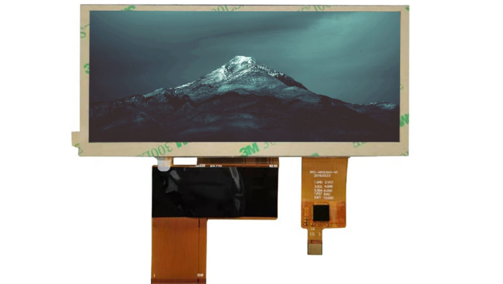
Replacing a mirror with a camera and a screen changes the display from a convenience into a regulated viewing device. Type approval for a camera monitor system tests what the driver can see, in specified light and weather conditions, from a specified eye position – and the display is a direct participant in every one of those measurements. That reframes the specification: this is an optical and temporal performance problem before it is a screen procurement problem.
What UNECE R46 and ISO 16505 demand from the display
They demand specified visibility, not specified hardware.
Regulation for mirror replacement in Europe is built around UNECE Regulation No. 46 and the ISO 16505 performance standard for camera monitor systems, which together define what the system must show and the conditions under which it is measured. The requirement is expressed in terms of the field of view, image quality, glare behaviour and response time of the complete system, so no single component carries the compliance claim – the display, camera, processing and mounting are tested as one.
In the United States, the equivalent visibility requirement for rear-view systems is set out in 49 CFR 571.111. Read the applicable regulation before writing the display specification; it determines which parameters are pass or fail and which are design choices. For programmes that also sell in Europe, the internal electronics of the display assembly still need to satisfy the safety and EMC framework, including the EU EMC Directive.
Field of view, magnification and pixel density
Pixel density follows from the required angular resolution.
The regulation sets the area the driver must be able to see; the display and camera together must deliver that area at a resolution the driver can interpret, which links screen size, viewing distance, camera field of view and sensor resolution. A larger screen does not automatically improve the result if the camera lacks the resolution or if the display cannot render the detail. The practical sequence is to fix the eye position and required field of view, derive the angular resolution, then select the camera and display together.
Two trap conditions are common in early designs: a display placed where the driver must refocus significantly compared with the mirror it replaced, and a screen whose usable area is reduced by bezel, curvature or a frame that intrudes into the regulated field of view. Both are geometry problems that no panel specification can fix.
Luminance, contrast and glare in direct sunlight
The screen must show an image, not a reflection.
Under direct sun the front surface of the display reflects ambient light back towards the driver, reducing the contrast of the image underneath. The countermeasures are the ones used across automotive displays – anti-glare treatment to spread reflections, anti-reflective coating to reduce them, and optical bonding to remove internal reflections – combined with enough luminance headroom. Because the display sits inside a cab where the driver’s eye position is fixed, the reflection geometry can be analysed early rather than discovered in a test vehicle.
CDTech’s notes on anti-glare and anti-reflective coatings for vehicle displays and on measuring sunlight readability describe how to specify and verify this instead of arguing about photographs.
Night operation: blooming, veiling glare and minimum luminance
Night performance fails on too much light, not too little.
At night, a bright display in the cab reduces the driver’s dark adaptation, and light from headlamps of following vehicles can wash out the camera image. The display-side requirements are a low minimum luminance that remains flicker-free, uniform dimming that tracks ambient light smoothly, and enough image contrast to distinguish a dim scene from a shadow. Blooming – where a bright source in the image spreads and obscures detail – is largely a camera and processing issue, but a display with poor black-level uniformity compounds it.
The relevant acceptance test is a real night drive with a following vehicle, not a chamber measurement. CDTech’s material on night mode display design for vehicle use covers the dimming and contrast approach that these systems share.
Latency budget from sensor to photons
The whole chain must stay inside the regulated response time.
Latency accumulates through sensor exposure, image processing, transmission, display timing and pixel response, and the requirement applies to the total rather than to any single stage. A useful budget allocates the allowed time explicitly: sensor and exposure, processing, link, display controller and panel response. Once the budget exists, interface choices become measurable: a compressed or long serial link adds decode or buffering delay, while a straightforward uncompressed path adds almost none.
Serialiser-deserialiser links are common in these systems because they carry video and control over a single coax pair with predictable latency; TI’s FPD-Link devices and Analog Devices signal-chain products document the design options. CDTech’s material on GMSL and FPD-Link for long-distance displays covers the cabling and reliability side of the same architecture.
Flicker, motion blur and the stroboscopic effect
Frame rate and pixel response decide whether motion looks continuous.
During a lane change, objects move quickly across the screen, and a display with slow response or a mismatched frame rate produces blur, tearing or a stroboscopic effect that makes judgement harder. The specification should set a maximum pixel response time at the operating temperature range, not at room temperature, and require the panel to accept the frame rate the processing chain produces without frame-rate conversion artefacts. Backlight dimming must also remain flicker-free across the range, because visible modulation at low luminance is more distracting than at high luminance.
Test motion behaviour with real footage at the intended vehicle speed, not with a static test image. Camera and display defects interact, and only realistic content exposes which stage is responsible.
Reliability for 24/7 fleet duty cycles
Commercial vehicles run their displays for more hours in a year than cars do in five.
A truck or bus mirror-replacement display may operate for ten or more hours a day, every day, in all weather, which multiplies backlight hours and thermal cycles compared with a passenger car. That changes the lifetime calculation: specify the backlight lifetime at the actual operating brightness and the enclosure temperature, and expect the display to be a serviceable item with a defined replacement procedure.
Moisture and dust resistance are equally important, and the rating belongs to the installed assembly. The definitions of the IP code are in IEC 60529; the sealing method – bonded front, gasket or sealed housing – should be specified explicitly, because the numbers alone do not describe a design.
Display mounting in a vibrating cab
Mounting design decides image stability as much as the panel does.
A cab vibrates continuously, and a display on a long bracket can develop movement relative to the driver’s eye that is far more distracting than a static misalignment. The mounting must be stiff, and the display must be qualified in that mounting, not on a bench. Cable retention matters too: an FPC or connector that works loose under vibration produces intermittent faults that are hard to reproduce in service.
Run vibration and shock tests on the display in its production mounting configuration, and record the test axis directions. A result obtained flat on a bench does not transfer to an assembly mounted on a cab pillar.
Winter and dirt: what the display cannot fix
The display cannot compensate for an obscured camera.
Winter operation is dominated by camera and lens conditions: snow, salt spray, condensation and low sun. A heated lens or washer system is a system-level decision, but the display specification should account for it – for example by keeping sufficient contrast when the image is low-contrast and by avoiding aggressive image processing that amplifies noise in a dirty scene. The display’s own winter issue is cold-start behaviour and any fogging inside the front assembly, which is eliminated by bonding and controlled by the sealing design.
Document the cold-start visibility requirement as part of the system specification, because type approval and fleet acceptance often hinge on what the driver can see in the first seconds after ignition on a cold morning.
Validating a CMS display before type approval
Validate the system, at the vehicle, in the conditions the regulation names.
The pre-approval validation set should include sunlight and low-sun conditions, night driving with following headlamps, rain and spray, motion behaviour during lane change, cold-start timing, and vibration in the installed mounting. Each test should record the system configuration, including display brightness settings and any processing enabled, because approval results are only valid for the configuration tested. The SAE standards programme maintains many of the test methods used for these measurements in North America.
Involve the display supplier early enough to change the stack – coating, bonding and brightness headroom – rather than late enough only to adjust firmware. The parameters that determine approval are physical, and they are cheapest to set before tooling.
FAQ
What is a camera monitor system display requirement in practice?
It is a performance requirement on the complete system: a defined field of view, image quality, glare behaviour, night performance and response time, measured from a specified eye position in specified conditions. The display contributes to all of them, but no display specification alone can establish compliance.
How bright must a CMS display be at night?
The night problem is usually too much brightness rather than too little, because a bright screen in the cab reduces the driver’s dark adaptation. Specify a low, flicker-free minimum luminance with smooth ambient tracking, and validate on a real night drive rather than in a chamber at a fixed light level.
What latency is acceptable from camera to display?
The acceptable total is set by the applicable regulation or customer requirement applied to the whole chain, from exposure to photons. Build an explicit budget across sensor, processing, link, controller and pixel response, then choose interfaces that fit inside it; compressed or buffered links consume much of the allowance.
Can a standard automotive TFT module be used in a mirror-replacement system?
Often yes, provided the module meets the brightness, dimming, response-time and viewing-angle requirements and is integrated with the right coating and bonding. The limiting factors are usually night dimming quality, low-temperature response and the mechanical mounting rather than the panel technology itself.
Next step
Send the regulated field of view, eye position and mounting envelope to CDTech for a display proposal that states brightness, dimming range, coatings and bonding method against the approval conditions.
Contact sales@cdtech-lcd.com or use the contact page; automotive and commercial vehicle modules are listed under vehicle LCD displays.
Related articles
 ESD Protection for Display Modules: Design, Test and Field RealityInfo
 Hydrogen, Gas and Chemical Process Displays: Where Certification Drives the DesignInfoResistive Touch Screens: Where They Still Beat Capacitive in 2026Info
 Haptic Feedback and Display UX in Industrial Equipment: When Touch Is Not EnoughInfo