FPC and Connector Design for Displays: Preventing the Most Expensive Field Failure
FPC and connector design for displays: bend radius, strain relief, shielding, contact reliability and the field failures that good design prevents.
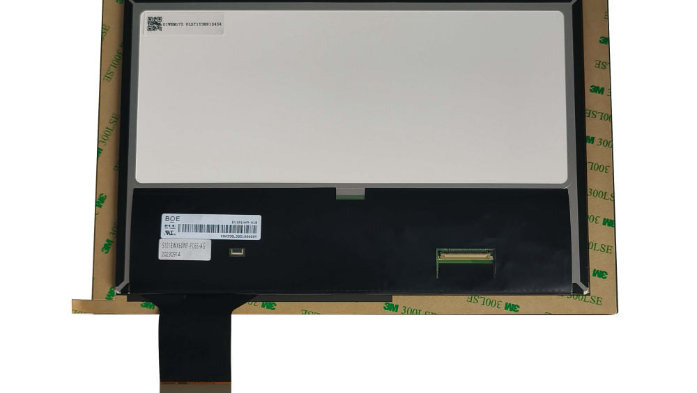
The most expensive display failures are not panel failures. They are the intermittent ones caused by a flex circuit that fatigued, a connector that fretted, or a cable exit that carried load it was never designed for – faults that appear months into service, resist diagnosis and damage the reputation of the product rather than the part.
Why the interconnect is the weak point
It concentrates every mechanical exposure in one component.
A display’s flexible circuit carries the electrical interface and, in many designs, the mechanical connection between two parts that move relative to each other. It sees the assembly process, the mounting loads, thermal expansion differences and any handling during service. Copper on a flexible substrate has a finite fatigue life, and the failure is progressive: microscopic cracks, then intermittent contact, then an open circuit. Because the progression produces intermittent symptoms, the fault is usually reported as “sometimes the screen goes blank”.
Good design does not eliminate fatigue; it places the movement where the copper can tolerate it.
Bend radius and the number of bend cycles
Bend radius is a specification, not a guideline.
Every flex design has a minimum bend radius for a dynamic application and a different, smaller one for a static bend. The practical numbers depend on the construction, the copper thickness and the number of layers, and they should come from the FPC supplier rather than from experience. Where the circuit bends during assembly only, a static radius is sufficient; where it bends during service, the dynamic radius applies and the cycle count becomes part of the requirement.
Specifying the radius in the drawing, and enforcing it with a fixture or a physical stop during assembly, is what converts the number from advice into practice.
Strain relief and cable routing
Load should be carried before the connector.
A cable that hangs from a connector, or an FPC that is the only mechanical path between two parts, will eventually damage the joint. The standard measures are a clamp or a foam block that takes the load before the connector, a service loop that absorbs movement, and a routing that avoids sharp edges and heat sources. In handheld and moving products, the cable should be routed so that the movement it experiences is bending along its length rather than tension at its termination.
CDTech’s material on FPC cable design and on preventing flicker and EMI through cable design covers the electrical side of the same routing decisions.
Shielding, grounding and return paths in a flex
A flex is a transmission line with a ground plane, or it is not.
Where the interface is differential, the flex should maintain consistent impedance and a continuous reference plane beneath the pairs. Where it is not, the return path still matters: a return that wanders around the circuit creates loops that radiate and pick up noise. Shielding layers add cost and thickness but are the practical answer for high-rate interfaces in noisy environments. The decision should be made with the interface and the environment in view, not added later as a remedy.
Where the display also carries touch signals, keeping those conductors away from the backlight drive lines within the flex is as important as the external routing.
Connector selection for the application
Four parameters decide the part number.
| Parameter | Why it matters |
|---|---|
| Pitch and pin count | Determines board space and assembly method |
| Mating cycles | Matches the service regime; critical for field-replaceable displays |
| Retention | Prevents vibration-induced disconnection; locking or friction lock |
| Plating | Corrosion resistance in humid or chemically exposed installations |
Where the connector is not field-serviceable, the mating cycle requirement is low and cost dominates. Where the display is replaced in the field, the opposite applies, and a positive lock with a documented cycle rating is worth the extra cost. Connector makers such as Hirose and JAE document these parameters for their product families.
Fretting, oxidation and contact resistance
Contacts fail slowly and intermittently.
Vibration causes small relative movements between mating contacts, which wears the plating and allows oxidation; the result is a slowly rising contact resistance and intermittent behaviour. Gold plating on both halves reduces the problem, as does a connector design that maintains contact pressure under vibration. Where the environment is humid or chemically exposed, plating choice becomes a corrosion decision rather than an electrical one.
Because fretting is progressive, a unit that passes an initial test can fail after months. Vibration testing with continuity monitoring during the run is the test that exposes it.
Assembly and service considerations
Design for the person assembling and the person repairing.
An FPC that requires a delicate insertion at an awkward angle will be damaged during assembly, and one that cannot be disconnected without removing other parts will be damaged during service. The practical requirements are a connector that can be mated with a defined insertion force and a positive lock, enough slack to work with, and clear marking of orientation. Where a ZIF connector is used, the actuator should be accessible and its position unambiguous.
Adding a note to the assembly drawing about the insertion direction and the maximum bend radius costs nothing and prevents a recurring assembly defect.
Test methods that predict field behaviour
Continuity monitoring under stress is the key technique.
- Bend cycle testing at the specified dynamic radius, with continuity monitoring.
- Vibration testing with resistance measurement on the signal and power conductors.
- Thermal cycling with the assembly in its mounting, monitoring for intermittent opens.
- Mating cycle testing on the connector to the specified count.
- Inspection of the flex termination under magnification after each test.
Monitoring during the test is what distinguishes a passing design from one that is about to fail; a functional check after the fact misses intermittent opens that occur only under load.
Field failures that good design prevents
Four symptoms with known causes.
A display that blanks when the cable is moved indicates fatigue at the flex termination or the connector. A display that fails only in humid weather indicates oxidation or contamination at the contacts. A display that develops intermittent colour faults indicates a marginal conductor rather than a panel fault. A display that fails after a service visit indicates handling during reassembly, and points to a design that is difficult to service. Each of these is cheaper to prevent than to diagnose in the field, and all four are addressed by the design rules above.
CDTech’s notes on connector and contact reliability cover the joint-level failure analysis that supports these conclusions.
FAQ
What is the minimum bend radius for a display FPC?
It depends on the construction, copper thickness and layers, and there are separate values for static and dynamic bending. Obtain the figure from the FPC supplier, specify it in the drawing, and enforce it with a fixture or a physical stop during assembly so the number is respected in production.
Why do display connectors fail intermittently?
Usually through fretting: small relative movements under vibration wear the plating and allow oxidation, raising contact resistance progressively. Gold plating on both halves, adequate contact pressure and a positive lock reduce the effect, and vibration testing with continuity monitoring exposes it.
Should a display flex circuit be shielded?
Where the interface is high-rate or the environment is electrically noisy, a shield with a continuous reference plane is usually required to control both emissions and immunity. The decision should follow the interface and the environment, not be added later as a remedy for a discovered problem.
How do I test an FPC for field reliability?
Bend cycle testing at the dynamic radius with continuity monitoring, vibration testing with resistance measurement, thermal cycling in the production mounting, and mating cycle testing on the connector. Monitoring during the test is what reveals intermittent opens that a post-test functional check misses.
Next step
Send the mechanical arrangement, service regime and interface speed to CDTech; the reply will propose an FPC construction, bend radius and connector specification for the application.
Contact sales@cdtech-lcd.com or use the contact page.
Related articles
 ESD Protection for Display Modules: Design, Test and Field RealityInfo
 Hydrogen, Gas and Chemical Process Displays: Where Certification Drives the DesignInfoResistive Touch Screens: Where They Still Beat Capacitive in 2026Info
 Haptic Feedback and Display UX in Industrial Equipment: When Touch Is Not EnoughInfo