Automotive Display Packaging: Surviving Vibration, Shock and Thermal Cycling in a Moving Vehicle
Automotive display vibration and shock: where assemblies fail, random versus sinusoidal testing, FPC fatigue, backlight resonance and validation planning.
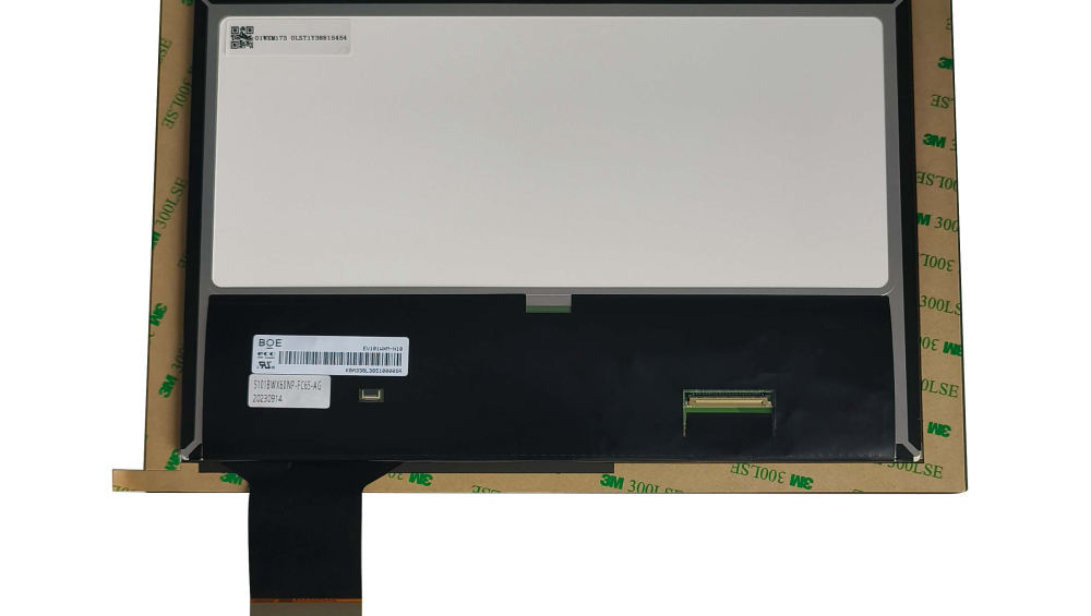
Vibration rarely breaks a display panel. It breaks the joints around it: the FPC bond, the connector contact, the soldered component on the controller board, the adhesive bead at the edge of the glass. That distinction matters because the fix is usually a mechanical design change costing nothing per unit, while a panel upgrade is expensive and often irrelevant.
Where vibration damage actually starts in a display assembly
At mass discontinuities and unsupported spans.
Damage concentrates wherever a stiff part meets a flexible one: the FPC where it leaves the glass, the connector where the cable is clamped, the solder fillet on a large component, and the corners of a bonded assembly where the adhesive carries load. The second pattern is resonance: a light guide, a shielding plate or a long cable that has a natural frequency inside the test band will amplify the input and fail long before the panel reaches its own limit.
A useful review question is which parts of the assembly are supported at both ends and which are cantilevered. Cantilevered mass is where vibration finds a failure; adding a clamp, a foam damper or a short strain-relief loop usually removes it. CDTech’s notes on mounting design and load paths and on connector and contact reliability cover the mechanical patterns that recur across programmes.
ISO 16750-3, IEC 60068-2-64 and OEM-specific profiles
The profile, not the standard number, determines the result.
Vehicle programmes usually reference a generic environmental standard family for electrical and electronic equipment in road vehicles, such as the ISO 16750 series, and a general vibration test method family such as IEC 60068-2-64 for random vibration. In practice the binding profile is the vehicle manufacturer’s own, because it encodes the mounting location: a display on a cab pillar sees a very different spectrum from one in a dashboard. The standard tells you how to test; the profile tells you what matters.
Ask for the profile in engineering units – acceleration spectral density bands, frequency range, duration and axes – not as a standard name. A supplier that reports “passed ISO 16750” without the profile in the report has performed a test you cannot compare with anything. The SAE standards programme maintains many of the automotive test methods referenced alongside these families.
Random vs sinusoidal testing and what each reveals
Random finds resonances; sinusoidal characterises them.
Random vibration excites all frequencies at once and is the realistic representation of road input, so it is the primary qualification test. Sinusoidal sweeps are used to find and characterise resonances, and a resonance search before the random run is what turns an unexpected failure into an explained one. Shock pulses, meanwhile, represent discrete events – potholes, door slams, kerb strikes – and are specified as a peak acceleration, a duration and a waveform.
Run the resonance search with accelerometers on the FPC, the cover glass edge and the largest component, not only on the fixture. The most useful output of the whole test programme is a list of the assembly’s resonances and their amplitudes, because that list is what a mechanical engineer can design against.
FPC, connector and solder joint fatigue
Every unsupported millimetre of flexible cable is a fatigue test.
An FPC that is fixed at the panel and fixed at the board with no strain relief converts vibration into bending at the stiffest point, which is usually the bond area. The standard countermeasures are a longer loop, a bend in the free length, a foam pad to damp the cable, and a clamp that holds the cable before the connector. On the controller board, large components with stiff terminations are the first to crack, and adding a compliant attachment or relocating the component away from the highest-response area is cheaper than changing the material.
Post-test inspection should include the bond area under magnification and a continuity check through the cable while flexed, not just a functional power-on. Standards for the workmanship and inspection of these joints are published by IPC.
Backlight and light-guide resonance
A light guide is a plate on soft supports, and it moves.
Backlight stacks are built from thin plates separated by air, held at the edges, and often supported on plastic or foam. Under vibration the plates move relative to each other, which shows as brightness flicker, a visible moire pattern, or a chafing mark after long exposure. The symptom is easy to mistake for an electrical fault because it appears as a luminance change during the test.
Countermeasures are mechanical: controlled preload, damping pads at the plate edges, a stiffer rear cover, and avoiding a design where the light guide is free to move in the direction of the dominant vibration axis. Where a display shows intermittent brightness variation in a vehicle but not on a bench, the backlight stack is the first place to look.
Adhesive and gasket compression set over time
Adhesives relax, and the seal follows.
Bonding adhesives and gaskets are viscoelastic: under sustained compression they relax, and under vibration they creep. The consequence is a slow loss of preload, which first appears as a slightly loose glass or a marginal seal and later as ingress or delamination. Thermal cycling accelerates the process, which is why vibration and thermal tests are far more informative when combined than when run separately.
Specify compression set limits and the material grade rather than a generic adhesive, and verify the change after cycling. Adhesive suppliers such as Henkel publish the viscoelastic data behind these choices, and matching that data to the drawing is the check that catches a substitution before it ships.
Shock pulses from potholes and door slams
Shock is about peak force at a joint, not about the panel.
A pothole or a door slam produces a short, high-amplitude pulse whose effect depends on how the display is mounted. A display on a compliant bracket absorbs the pulse by moving, which can be worse for the cable than a rigid mount. The relevant design questions are where the peak load path runs, which joints see the load, and whether the cover glass is supported behind the impact area.
Test shock in the production mounting configuration, and include the cable and connector in the test setup, because a shock test on a bare module proves less than it appears to.
Design countermeasures that do not add cost
Most fixes are geometry.
- Shorten cantilevered mass: move the connector closer to a support point.
- Add a controlled bend or loop in the FPC instead of routing it straight and taut.
- Damp cable runs with a foam pad rather than a rigid clamp at a single point.
- Preload the light guide and add edge damping to keep the stack from moving.
- Support the cover glass behind the area most likely to be struck.
- Keep heavy components off the region of highest board response.
None of these change the bill of materials materially, and each one removes a known failure mode. Their absence, rather than the panel specification, is the usual reason a module fails a vibration test.
Correlating lab tests with field failures
Field failures tell you which test was missing.
When a vibration-related failure appears in the field, the analysis should identify the failing joint, the axis and the vehicle conditions, then check whether the qualification profile covered that combination. Frequently the answer is that the test was run in one axis, or on a bench fixture rather than the production mounting, or with a shorter duration than the field exposure. Closing that loop is what turns a test programme into a predictive tool.
Keep the failure analysis structured, with the failed joint photographed and the test record attached. The same evidence is what a customer’s quality team will ask for, and it is what supports a change to the design rather than a change to the test specification.
A validation matrix for a new automotive display module
Cover three axes, two profiles and the production mounting.
| Test | Purpose | Key record |
|---|---|---|
| Resonance search, three axes | Find assembly resonances before qualification | Frequency, amplitude, instrumented locations |
| Random vibration, production mounting | Qualify against the vehicle profile | Profile in engineering units, duration, axes |
| Shock pulses | Verify joints under discrete events | Peak acceleration, duration, waveform |
| Combined thermal and vibration | Expose adhesive and gasket relaxation | Temperature profile, cycle count |
| Post-test inspection | Detect latent damage | Bond area images, continuity under flex |
| Optical re-measurement | Catch stack movement and uniformity change | Luminance and uniformity against the pre-test baseline |
Test houses and chamber suppliers such as Thermotron and Weiss Technik document the capabilities needed for combined profiles; the useful question for a supplier is whether the combined run is done in one chamber with the display powered, because that is where the realistic failures appear. CDTech’s quality certifications page lists the quality system scope that supports these test programmes.
FAQ
What vibration standard applies to automotive displays?
Programmes commonly reference the ISO 16750 series for road-vehicle electronics and IEC 60068-2-64 for random vibration test methods, but the binding profile is usually the vehicle manufacturer’s own because it encodes the mounting location. Ask for the profile in engineering units, not the standard number alone.
Why does a display flicker during vibration testing?
Usually because the backlight stack is moving: light guide, diffuser and reflector plates shift relative to each other, changing the optical coupling. Chafing marks and brightness variation in the same test point confirm it. Preload, edge damping and a stiffer rear cover are the usual remedies.
Should vibration and thermal tests be run separately or combined?
Both, but the combined run is more revealing for adhesives and gaskets. Thermal exposure relaxes the bonding material while vibration applies the load, which is closer to service conditions. Separate runs remain useful for isolating which factor caused a failure.
How do we stop display FPC failures in the field?
Give the cable a controlled path with strain relief rather than fixing it rigidly at both ends, damp it with a foam pad, and clamp it before the connector. Most FPC field failures are fatigue at the bond area caused by unfiltered bending, and they are resolved by geometry rather than by material upgrades.
Next step
If a module is failing vibration or showing intermittent behaviour in service, CDTech can review the mounting, FPC routing and backlight stack together with the test profile and propose mechanical changes before any material change.
Send the test report and assembly drawing to sales@cdtech-lcd.com, or start from the contact page.
Related articles
 ESD Protection for Display Modules: Design, Test and Field RealityInfo
 Hydrogen, Gas and Chemical Process Displays: Where Certification Drives the DesignInfoResistive Touch Screens: Where They Still Beat Capacitive in 2026Info
 Haptic Feedback and Display UX in Industrial Equipment: When Touch Is Not EnoughInfo