Sensors and Displays Converging: Integrating Touch, Light and Proximity Into One Module
Integrating touch, light and proximity sensing into one display module: the benefits, the interference problems and how to specify the combination.
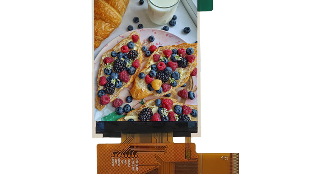
Combining an ambient light sensor, a proximity sensor and a touch panel with a display is attractive: fewer parts, one assembly, one calibration. It also creates interactions that do not exist when the sensors are separate – a light sensor that measures the backlight rather than the room, a proximity sensor triggered by the cover glass, a touch sensor disturbed by the sensor’s drive. These are predictable and manageable, but only if they are designed for.
Why integrate sensing into the display
Four benefits, all real.
- Fewer components and connectors, reducing assembly cost and failure points.
- A single aperture in the enclosure, simplifying the front design.
- Sensors behind the cover glass, protected from dust, water and damage.
- One supplier responsible for the assembly, including its calibration.
The benefits are largest in products where the front is sealed or exposed, because the alternative is an aperture with its own sealing and a sensor that can be damaged.
The ambient light sensor problem
It is inside the thing that emits light.
An ambient light sensor placed behind the cover glass next to a display is exposed to the display’s own backlight, which reflects internally within the stack. The result is a reading that rises when the screen brightens, causing the display to dim when it should brighten. The design responses are optical: place the sensor where the internal reflection is lowest, use an optical barrier between the sensor and the display’s backlight path, and calibrate the sensor’s response with the display at known brightness levels. Where the cover glass is printed, the print must include a clear window for the sensor, which is a print-layer decision.
Self-calibration during operation – subtracting the known contribution at each brightness setting – is usually necessary, which means the sensor’s behaviour must be characterised with the display, not separately.
The proximity sensor problem
Its detection threshold depends on the cover glass.
An infrared proximity sensor behind glass must distinguish a nearby object from the glass itself and from the print, and its threshold changes with glass thickness, coating and the print layout. A sensor calibrated on a bare module can behave differently once bonded, which is why the proximity function should be specified and validated as part of the assembled stack. Where the product also has a touch panel, the two sensing systems operate at different frequencies, which must not interact.
The practical approach is to specify the sensing distance required in the assembled product and to validate it with the production front, rather than to accept the sensor’s datasheet figure measured in free air.
Interference between sensing systems
Three systems in one assembly.
| Interaction | Symptom | Mitigation |
|---|---|---|
| Backlight switching into the light sensor | Brightness moves the wrong way | Optical barrier; calibration against brightness |
| Backlight switching into the touch sensor | Touch faults at certain brightness levels | Frequency selection; separation; defined return paths |
| Proximity emitter into the touch sensor | Phantom touches when the emitter pulses | Time-sharing between sensing systems |
| Touch drive into the light sensor | Slow drift in ambient readings | Filtering and averaging; physical separation |
Each of these is a signal-integrity problem with a layout or firmware answer, and each is much cheaper to address during design than after a product is in service.
Mechanical and optical design of a combined front
The front assembly is the critical part.
A combined front requires a clear window for the light sensor, a window or an infrared-transparent region for the proximity sensor, and a touch sensor pattern that leaves those areas unoccupied. Because the touch pattern usually spans the whole glass, the sensor windows must be designed into the electrode artwork, and the print must align with both. The cover glass thickness then has to satisfy the touch requirement and the proximity sensor’s detection range at the same time, which is often the constraint that decides the design.
Bonding the stack removes internal reflections that would otherwise interfere with both optical sensors, and it stabilises the dielectric stack for touch.
Calibration and configuration management
More sensing means more configuration.
A combined module carries parameters for touch tuning, light sensor response and proximity thresholds, all of which depend on the specific stack. Those parameters must be versioned with the module and the firmware, and a replacement module must be programmed to match. Where the parameters live in the host, the module’s identity must be recorded so the correct set is applied; where they live in the module’s controller, the configuration must be part of what the supplier delivers.
A configuration document that lists the stack, the firmware versions and the parameter sets is the practical instrument that keeps a fleet consistent.
Validation of the combined assembly
Each function and each interaction.
- Touch grid test with the sensor windows present in the artwork.
- Ambient light response measured with the display at defined brightness levels.
- Proximity detection range measured through the production cover glass and print.
- Cross-interference test with all sensing systems and the backlight active.
- Temperature and humidity cycling with functional checks of each sensor.
- Repeat after any change to the glass, print, coating or firmware.
Running these as a set, rather than one at a time, is what catches the interactions that a per-sensor test misses.
When to keep the sensors separate
Integration is not always the answer.
- When the light sensor must measure the true ambient level with no display contribution.
- When the proximity sensor needs a large detection range that a thick bonded glass prevents.
- When the front is not a single part and the sensors can be placed independently.
- When the product’s volume is low and the tooling for a combined front is not justified.
In those cases a separate sensor in its own aperture is often simpler, and the sealing and durability requirements can be met with a gasket or a bonded window of its own.
Specification items for a combined module
Six things to state explicitly.
| Item | Specify |
|---|---|
| Sensor positions | Location relative to the active area and the print |
| Sensor windows | Clear or infrared-transparent areas in the print and electrode artwork |
| Cover glass | Thickness, coating and transmission at the sensor wavelengths |
| Light sensor | Response range and the calibration against display brightness |
| Proximity | Detection range measured through the production front |
| Time-sharing | Sequence between sensing systems and the backlight driver |
Specifying these removes the ambiguity that otherwise appears during integration. Measurement and calibration practice for the optical side is described in CDTech’s notes on measuring brightness and uniformity, and touch tuning in touch controller selection and tuning. Static-control practice for the assembled module is published by the EOS/ESD Association.
FAQ
Can an ambient light sensor work behind a display cover glass?
Yes, with optical separation from the backlight path and calibration against the display’s brightness, because internal reflections otherwise make the reading rise as the screen brightens. The sensor also needs a clear window in the print, which is a print-layer design decision.
Why does a proximity sensor behave differently after assembly?
Because its threshold depends on the cover glass thickness, the coating and the print, and internal reflections change the signal. Specify the detection range in the assembled product and validate it with the production front rather than relying on a free-air figure.
Do touch and light sensors interfere with each other?
They can. Backlight switching disturbs both, proximity emitters can cause phantom touches, and the touch drive can introduce slow drift into ambient readings. Mitigations are optical barriers, frequency selection, defined return paths and time-sharing between sensing systems.
When is it better to keep sensors separate from the display?
When the light sensor must read true ambient light without display contribution, when proximity needs a range that thick bonded glass prevents, when the front is not a single part, or when volume does not justify the tooling for a combined front.
How should the sensing systems be sequenced?
Define a fixed sequence between the backlight driver, the touch scan and the proximity emitter, so that one is not active while another is measuring. Time-sharing removes most of the mutual interference and is simpler to validate than relying on filtering alone.
Next step
Send the sensing functions required, the front assembly design and the enclosure constraints to CDTech; the reply will state how the sensors can be integrated, what windows the print and artwork need and which interactions to validate.
Contact sales@cdtech-lcd.com or use the contact page.
Related articles
 ESD Protection for Display Modules: Design, Test and Field RealityInfoHydrogen, Gas and Chemical Process Displays: Where Certification Drives the DesignInfoResistive Touch Screens: Where They Still Beat Capacitive in 2026Info
 Haptic Feedback and Display UX in Industrial Equipment: When Touch Is Not EnoughInfo