Grounding and Shielding Design for Display Modules
EMC problems in display assemblies are usually described in terms of symptoms - a flickering image when a motor starts, a touch panel that misreads when a pump runs, a radiated emission failure at…
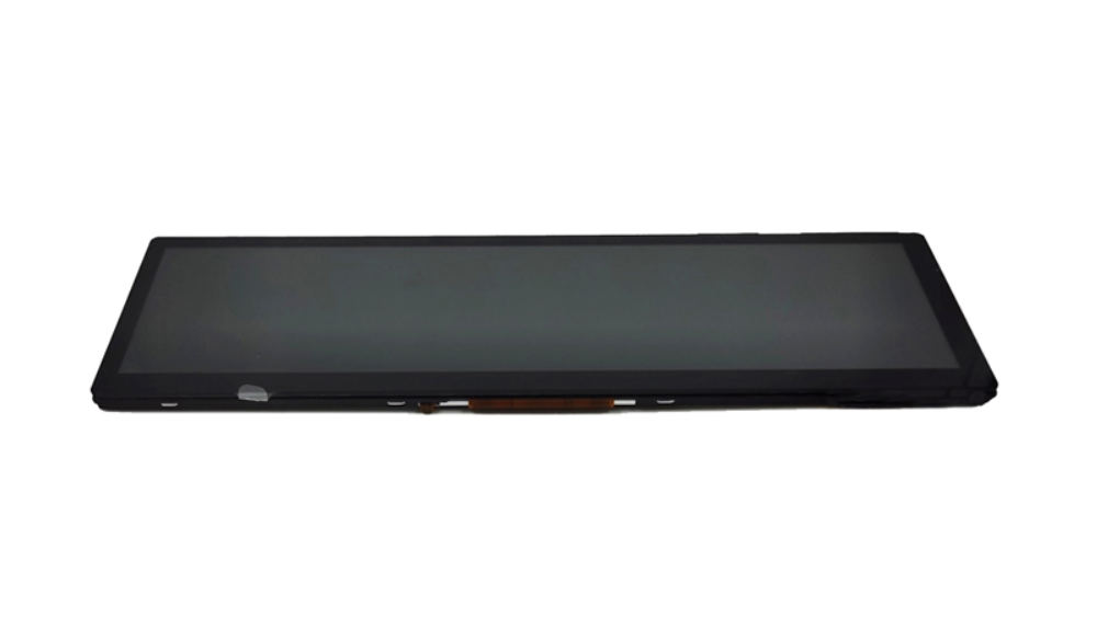
EMC problems in display assemblies are usually described in terms of symptoms – a flickering image when a motor starts, a touch panel that misreads when a pump runs, a radiated emission failure at a single frequency. The productive way to work is to trace the disturbance from its source through its coupling path to the victim, because each path has a different fix.
This article covers the grounding and shielding decisions that determine those paths, and the measurements that confirm a change has worked.
Grounding concepts inside a display assembly
A display assembly contains at least two grounds: the signal reference used by the interface and the chassis or mechanical ground of the housing. They may be connected at one point, at several points, or not at all, and that choice determines how noise currents flow.
The distinction that matters most is between a reference potential and a return path. A ground that carries signal return current is part of the circuit; a chassis ground is a shield. Confusing the two is the origin of most intermittent EMC problems in displays.
Single-point versus distributed grounding
The frequency at which a single-point scheme stops working depends on the geometry, not on a fixed number. A short, wide connection behaves as a single point well into the hundreds of megahertz; a long, thin one stops behaving as a point at far lower frequencies. Judging the design by the physical length of the connection is more useful than applying a rule of thumb.
The frequency at which a single-point scheme stops working depends on the geometry, not on a fixed number. A short, wide connection behaves as a single point well into the hundreds of megahertz; a long, thin one stops behaving as a point at far lower frequencies. Judging the design by the physical length of the connection is more useful than applying a rule of thumb.
The frequency at which a single-point scheme stops working depends on the geometry, not on a fixed number. A short, wide connection behaves as a single point well into the hundreds of megahertz; a long, thin one stops behaving as a point at far lower frequencies. Judging the design by the physical length of the connection is more useful than applying a rule of thumb.
The frequency at which a single-point scheme stops working depends on the geometry, not on a fixed number. A short, wide connection behaves as a single point well into the hundreds of megahertz; a long, thin one stops behaving as a point at far lower frequencies. Judging the design by the physical length of the connection is more useful than applying a rule of thumb.
Single-point grounding connects all returns to one reference. It prevents low-frequency ground loops, which is why it is conventional in analogue and low-speed circuits. At high frequencies, however, the impedance of the connecting path becomes significant and a single point no longer behaves like a single point.
Distributed grounding connects returns to a plane at many points. It works well at high frequency because the plane presents a low impedance, but it can create loops if the connections are made at points that are not actually at the same potential.
Display assemblies usually need both ideas at once: a defined signal reference for the interface, and a chassis that is bonded to the housing at several points for shielding. The design decision is where those two meet, and it should be made deliberately rather than left to the connector pinout.
Shield termination and bonding techniques
A shield works only if it is terminated properly. A cable shield connected by a single wire at one end – the classic “pigtail” – behaves as an antenna rather than a shield at the frequencies that cause radiated emissions.
Effective termination means 360-degree bonding to the chassis: a conductive clamp, a shielded backshell, or a connector whose shell contacts the housing around its circumference. Where a full bond is impractical, a short, wide connection is far better than a long, thin one, because the inductance of the termination path is what limits its effectiveness.
Paint, anodising and powder coating are insulators. Any bonding point needs bare metal contact, protected afterwards against corrosion, or the shield is terminated to a painted surface and does nothing.
Cable routing and return paths
Most display-related emissions come from cables, not from the panel. A flat cable carrying a pixel clock radiates efficiently, and its return path is usually part of the same connector – which means the loop area is set by the cable design.
Three routing rules follow. Keep the signal and its return in the same cable and as close together as the construction allows. Route display cables away from high-current switching wiring and from any cable that carries motor or solenoid current. And where a cable must cross a noisy area, cross at right angles rather than running parallel.
The FPC cable design guidance covers how the cable’s own construction affects the loop area and the resulting emissions.
Interaction with touch sensing
Immunity is the other half of the problem, and the measures used for ESD and EMI immunity on touch screens overlap with the grounding choices here. Touch controllers are sensitive to noise in the same frequency range that switching regulators and backlight drivers produce. A display can pass radiated emission limits and still have a touch panel that misreads under load, because the coupling path is internal rather than radiated.
The usual contributors are a noisy supply rail shared with the touch controller, a ground return that carries backlight current under the sensor, and inadequate filtering on the touch controller’s own supply. Separating the touch controller’s supply and its return from the backlight path often resolves symptoms that no amount of shielding fixes.
Grounding metal bezels and housings
A metal bezel can be an asset or a problem. Bonded to the chassis at several points, it extends the shield and reduces emissions from the panel edge. Bonded at one point, or bonded to a different reference than the cable shield, it becomes a radiating element or an antenna that feeds noise into the panel.
The decision is not whether to bond, but where and how many times. Bonding at the same points that provide mechanical support is convenient and usually electrically sound, provided the contact is bare metal and the fastening force is stable.
Mistakes that create loops and antennas
| Mistake | What it creates |
|---|---|
| Shield terminated by a long pigtail | An antenna that radiates the noise it should be containing |
| Shield bonded to a painted surface | No electrical connection at all |
| Signal return routed separately from the signal | A large loop area and high emissions |
| Multiple ground connections between units at different potentials | Ground loop current in the shield and the signal return |
| Display cable run parallel to motor wiring | Capacitive and inductive coupling into the interface |
| Touch supply shared with the backlight driver | Internal coupling that shielding cannot fix |
Measuring noise before and after a change
Measurements are only comparable if the setup is repeatable. Fix the probe position, the supply conditions and the display content, and record them with the result. A near-field scan taken with a probe held in a slightly different position can differ enough to hide or exaggerate the effect of the change you were testing.
Measurements are only comparable if the setup is repeatable. Fix the probe position, the supply conditions and the display content, and record them with the result. A near-field scan taken with a probe held in a slightly different position can differ enough to hide or exaggerate the effect of the change you were testing.
Measurements are only comparable if the setup is repeatable. Fix the probe position, the supply conditions and the display content, and record them with the result. A near-field scan taken with a probe held in a slightly different position can differ enough to hide or exaggerate the effect of the change you were testing.
Measurements are only comparable if the setup is repeatable. Fix the probe position, the supply conditions and the display content, and record them with the result. A near-field scan taken with a probe held in a slightly different position can differ enough to hide or exaggerate the effect of the change you were testing.
Changes should be measured, not assumed. Two measurements are practical without a full EMC laboratory: a near-field probe scan of the cable and the assembly, and a spectrum measurement of the noise on the supply rails at the display connector.
The value of these measurements is comparative. A near-field scan taken before and after a shield termination change shows whether the change had the intended effect, even when the absolute levels are not calibrated. Making one change at a time is what keeps the comparison meaningful.
Documentation for EMC testing
When the product goes to an accredited laboratory, the documented design decisions save time: the ground scheme, the shield terminations with their contact points, the cable types and routes, and the filter components with their placement. If a test fails, the laboratory can only help if it knows what was intended.
Record the configuration tested, including the cable length and routing, because an EMC result applies to the assembly that was tested rather than to the design in general. For the test items themselves, see the article on EMC testing for displays.
Noise-path worksheet
| Source | Coupling path | Measure that addresses it |
|---|---|---|
| Backlight driver switching | Supply rail shared with touch or interface | Separate filtering and return path |
| Pixel clock on a flat cable | Radiated from the cable loop | Cable construction, routing, shield bonding |
| Motor or solenoid wiring nearby | Capacitive and inductive coupling | Physical separation and crossing at right angles |
| Chassis potential difference between units | Shield current and ground loop | Single defined reference, or isolation |
| External field from an adjacent product | Radiated into the panel and cabling | Bezel bonding and enclosure continuity |
If a display assembly is failing EMC or behaving intermittently under load, describe the source, the symptom and the cable routing – the worksheet above usually narrows it to one or two paths before any test equipment is connected.
Frequently asked questions
Should the display cable shield be grounded at both ends?
Usually yes, when both ends are at the same chassis potential, because that is what makes the shield effective. Where the two ends are at different potentials, an isolating arrangement or a different scheme is needed to avoid shield current.
Can a noisy touch panel be fixed with shielding?
Sometimes, but the more common cause is a shared supply or return path with the backlight. Check the internal coupling before adding shielding.
Do we need a laboratory to improve EMC?
No. Comparative near-field and supply-rail measurements on the bench are enough to establish whether a change helped, with the laboratory used for the formal qualification.
Related articles
 OLED Versus LCD for Industrial HMI: Lifetime, Burn-In and FitInfo
 Display Timing Parameters Explained: Pixel Clock, Blanking and Sync for PractitionersInfoCustom Medical Displays: DICOM, Grayscale and Panel Selection ExplainedInfo
 Ventilator and Infusion Pump Displays: Design Constraints Nobody DocumentsInfo