Open-Frame Displays for Panel Builders: Mechanical, Thermal and Cable Design
Open-frame display integration: mounting patterns, cut-out tolerance, thermal design behind sealed glass, cable routing, grounding and field serviceability.
Open-Frame Displays for Panel Builders: Mechanical, Thermal and Cable Design
An open-frame display is not a product so much as an agreement about what is included. Two suppliers can use the same panel and deliver assemblies with different mounting patterns, different thermal behaviour and very different serviceability. Panel builders get into trouble when the datasheet is treated as the design and the integration decisions are made later, in the enclosure, where they are expensive.
What open-frame really means across suppliers
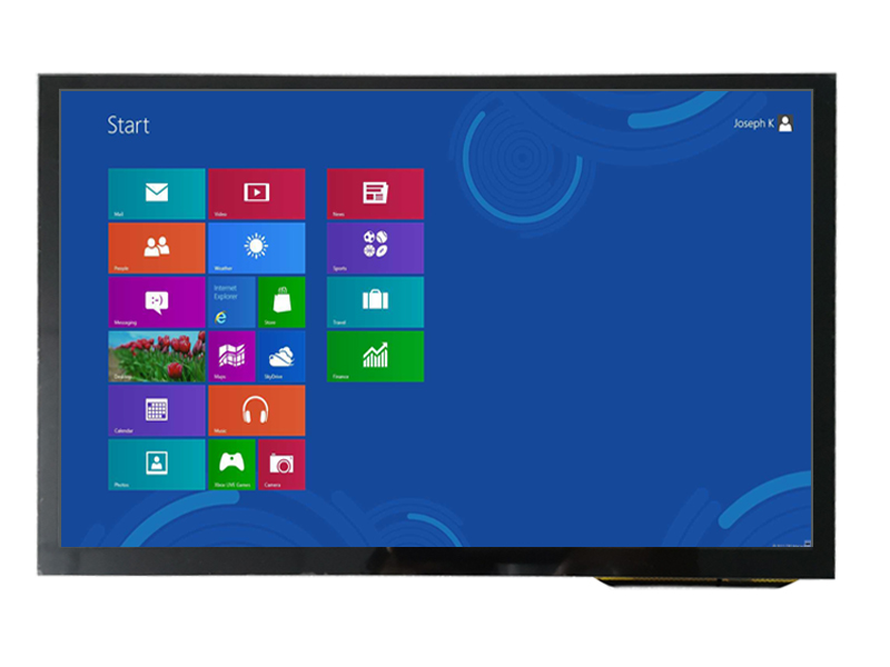
It means a panel assembly without a front bezel or enclosure.
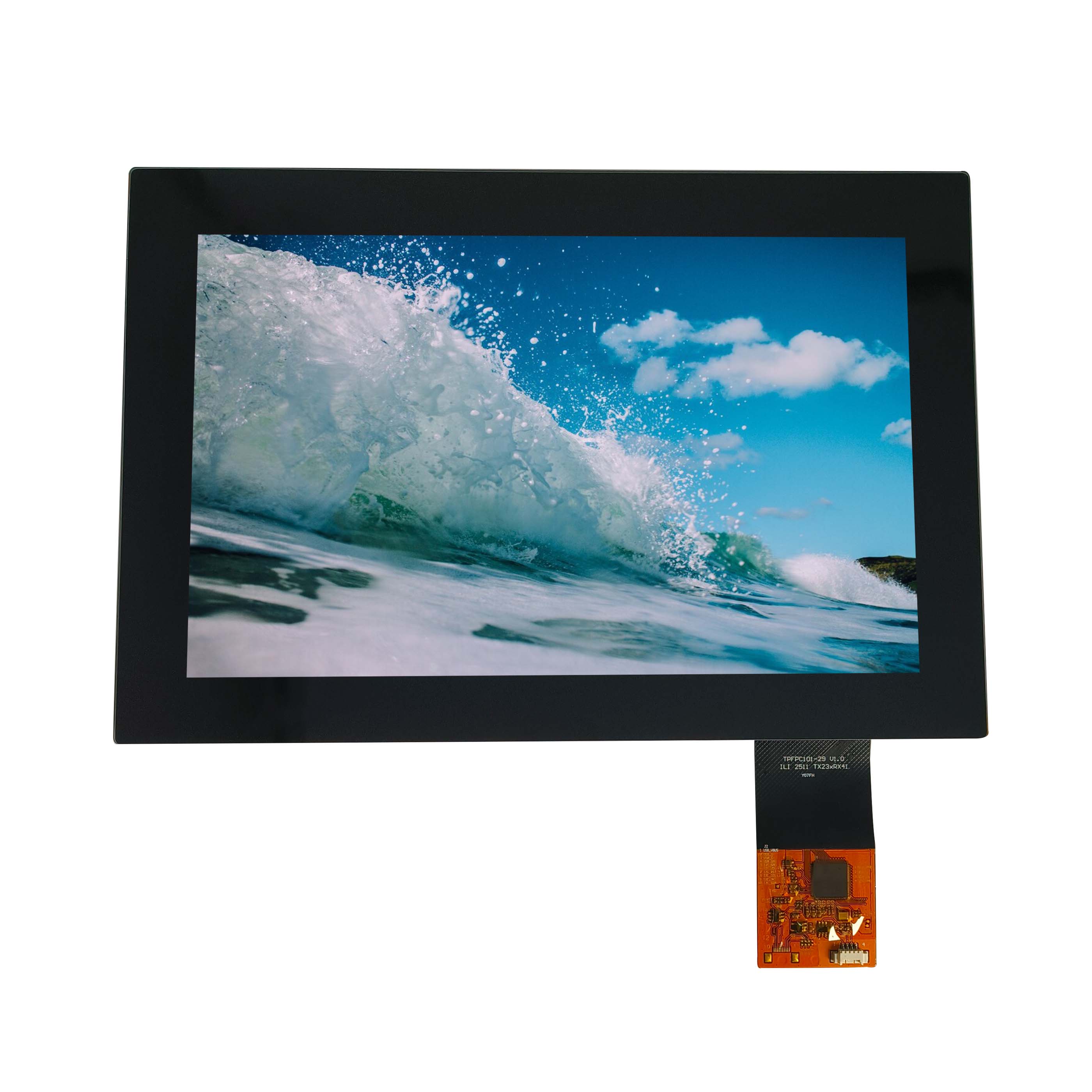
The common content is the display module, a backlight driver or interface board, a frame or bracket, and a cable or connector. What varies is whether the touch panel, cover glass, bonding, power supply and mounting hardware are included, and whether the frame is structural or simply a carrier. Those differences determine whether the integrator is building a mechanical design or assembling parts.
Ask for a boundary drawing that marks what the supplier delivers and what the integrator adds. The most common integration failures – a frame that flexes under load, a cable that cannot reach the controller, a display that overheats because the supplier’s bracket blocks the intended airflow – all originate from an unclear boundary.
Mounting patterns, bezel options and cut-out tolerances
Cut-out tolerance decides whether the front looks finished.
Panel-mounted displays usually reference a VESA-style or proprietary hole pattern, and the cut-out in the enclosure is the visible result. The tolerance stack includes the panel outline, the frame, the gasket compression and the enclosure fabrication, and errors appear as uneven gaps, a proud bezel edge, or a gasket that is not compressed uniformly and therefore leaks. Define the datum edges and the tolerance on each side rather than giving a single nominal cut-out dimension.
Where a gasket is used, the enclosure surface must be flat enough for a consistent seal; a gasket cannot compensate for a warped panel cut-out. Steel enclosures are usually flat enough, moulded plastic often is not, and composite panels vary. Where the enclosure surface is not reliable, an alternative sealing method – a bonded front assembly with a sealed rear housing – removes the dependency on the enclosure flatness.
Thermal design when the display sits behind sealed glass
Sealed enclosures turn the display into its own heater.
The backlight is the largest heat source inside a display assembly, and behind sealed glass there is no convection path to carry it away. The temperature rise above ambient depends on the enclosure volume, the internal surface area available for heat transfer and whether the display has a conductive path to the enclosure wall. Conduction through a metal frame to a metal wall is usually the most effective single measure.
Specify the maximum internal air temperature and verify it with a thermocouple test at full brightness in the worst-case ambient condition. CDTech’s material on thermal design for sealed display enclosures sets out the trade-offs between conduction, venting and brightness derating.
Ventilation, fans and condensation in an enclosure
Ventilation brings in moisture as well as air.
A fan reduces temperature but introduces dust and, in humid conditions, moisture that will condense on the coldest surface at night. Filtered fans with a defined filter maintenance interval are the usual compromise for indoor panels; for outdoor or washdown enclosures, a sealed design with conduction cooling and a controlled vent path is usually more reliable than forced air.
Where a vent is used, it should be filtered and placed so that water cannot enter, and the enclosure should be able to dry after a temperature cycle. The failure to design against is condensation on the display front or on the controller board, which produces intermittent faults that disappear when a technician opens the cabinet.
Cable routing, strain relief and service access
Assume the display will be replaced while the machine is installed.
Cable length should allow the display to be removed and set down beside the panel without disconnecting everything at once, with enough slack to reach a technician’s hand. Strain relief should hold the cable before the connector, and the routing should avoid sharp edges, moving parts and heat sources. Where the display is deep inside a cabinet, serviceability is often the deciding factor between a 15-minute and a two-hour repair.
Mechanical load paths matter as much as electrical routing: a display supported at four corners with a heavy cable hanging from one side will flex, and flexing shows up as uneven luminance or a cracked bond over time. CDTech’s material on mounting design and load paths covers these failure patterns.
Power supply and grounding practice
Ground once, deliberately, and keep the return path short.
Panel displays are often powered from the same supply as drives, relays and contactors, so the supply is electrically noisy and the return path is long. Good practice is a dedicated supply or at least a dedicated feed with local decoupling, a single defined ground reference, and shield terminations at one end only unless the installation justifies both. Backlight drivers are switching converters and should be treated as noise sources when their cables are routed near touch or video signals.
The safety requirements for the internal electronics of information technology equipment are commonly written against IEC 62368-1, and the EMC framework for equipment sold in Europe is set by the EU EMC Directive. Workmanship expectations for the wiring and assembly are published by IPC.
Ingress protection of the assembled front panel
The rating applies to the panel, not to the display.
An open-frame display has no IP rating by itself; the rating is achieved when the gasket, bezel, display and enclosure are assembled correctly. The definitions in IEC 60529 distinguish splash, jet and immersion, and the cleaning method in service decides which is required. Where the display is supplied with a gasket, the compression range must be stated, because too little compression leaks and too much deforms the gasket permanently.
Test the sealing on the assembled panel with the production gasket after thermal cycling. A seal that passes when new and fails after fifty cycles is the most common form of ingress complaint.
Touch integration and EMC inside a metal cabinet
A metal cabinet is both a shield and a coupling path.
Inside a steel enclosure the display’s own emissions are contained, which helps certification, but the cabinet also couples the display’s ground to everything else bolted to it. Capacitive touch is sensitive to that arrangement: a poor reference between the touch controller and the cabinet can make the panel feel unresponsive near the edges or produce phantom touches when a drive starts. Bonding the sensor reference to the cabinet at one deliberate point, and keeping touch cabling away from motor and drive cables, prevents most of it.
Where the front panel includes a metal bezel, its connection to the display ground should be documented. Ungrounded metal in contact with a capacitive sensor is a design variable, not an assembly detail.
Field serviceability: replacing a display without scrapping the unit
Design the replacement path before the first build.
Serviceability depends on three things: connectors that can be reached, mounting that can be undone without removing the machine’s other assemblies, and firmware that can be reconfigured without a proprietary tool. Where the display includes a controller board with calibration data, the replacement path should include how that data is transferred. Where the front panel is bonded and sealed, the practical service unit is the whole front assembly, so spares should be stocked at that level rather than as bare panels.
Document the replacement procedure and include it with the machine. The cost of a field replacement is dominated by the time to diagnose, not by the part.
Handover checklist from panel builder to end customer
Hand over the information that prevents avoidable service calls.
- Display part number, revision and the supplier’s contact path for replacements.
- Approved cleaning agents and methods, with the gasket material named.
- Environmental limits for the assembled panel, including the internal temperature limit.
- Brightness and contrast settings used in commissioning, with the reason if it was reduced.
- Replacement procedure, including firmware and calibration steps.
- Spare part recommendation over the machine’s service life.
This list takes an hour to produce and removes the most common source of warranty disputes: an end user who cleaned a sealed panel with the wrong chemical or replaced a display without transferring its settings. Service and calibration guidance from control platform suppliers such as Rockwell Automation is a useful template for the level of detail the handover should carry.
FAQ
What does open frame mean on a display datasheet?
It means the display is supplied without a front bezel or enclosure, usually with a carrier frame, interface board and cable. What is included beyond that varies between suppliers, so ask for a boundary drawing that marks the exact scope of supply before designing the enclosure around it.
How do I mount an open-frame LCD into a steel panel?
Use the supplier’s mounting pattern with a gasket whose compression range is stated, and make sure the enclosure surface is flat enough for a uniform seal. Define the cut-out with a tolerance on each side and datum edges, and support the assembly so that the cable weight does not load one corner.
How do I stop an enclosed display from overheating?
Give the backlight heat a conduction path to the enclosure wall, keep the internal air volume as small as the design allows, and consider reducing brightness in hot conditions. Forced air helps indoors but introduces dust and moisture; in sealed outdoor enclosures, conduction plus controlled venting is usually more reliable.
Can an open-frame display be IP65 rated?
Not by itself. The rating is achieved by the assembled front panel once the display, gasket, bezel and enclosure are combined correctly, with the gasket compressed within its specified range. Test the seal on the production assembly after thermal cycling, not on a new sample of the display alone.
Next step
Send the enclosure drawing, cut-out dimensions and thermal conditions to CDTech; the response will include a boundary drawing, gasket recommendation and heat-path proposal for the specific panel size.
Contact sales@cdtech-lcd.com or use the contact page. Panel and open-frame classes are listed under industrial LCD displays.
Related articles
 Sunlight-Readable Industrial Displays: How to Hit the Numbers in Real Ambient LightInfo
 Choosing an Industrial HMI Display for a Machine That Must Run 24/7 for Ten YearsInfo
 Digital Cockpit Displays: Specifying a Multi-Screen Architecture Without Reliability SurprisesInfo
 OLED Versus LCD for Industrial HMI: Lifetime, Burn-In and FitInfo