MIPI DSI Initialization Sequence: Separate DCS Commands from Vendor Registers
MIPI DSI initialization guide: source the exact panel revision table, separate DCS from vendor registers, validate delays and keep reproducible logs.

A panel that lights on one build and stays black on the next is often blamed on the DSI link. The link trains, the packets are acknowledged and the image still does not appear, because the initialization sequence belongs to a different panel revision. A MIPI DSI initialization sequence is a versioned artifact: part standard command set, part vendor register table, part timing. This guide separates the two command layers, shows how to validate the delays, and defines the package that makes a bring-up reproducible.
Where should a MIPI DSI initialization sequence come from?
Take the sequence from the panel supplier’s exact revision.
The table must come from the drawing or vendor document for that panel revision, not a similar module, because register values and delays are panel-specific.
The only defensible source is the supplier’s document for the exact panel and revision. That document defines the vendor commands, the gamma settings, the power timing, the sleep-out delay and the display-on sequence. A table copied from a similar module, a demo board or an online project may produce an image, but it is not evidence that the panel is operating within its specification.
The revision matters because a panel can change its driver IC, its gamma curve or its power sequencing without changing its outline or part number prefix. If the revision is not printed on the module or encoded in a readable register, the unit is not ready for a sequence. Ask the supplier for the revision and the matching table, and record both in the build documentation.
The sequence also depends on the host. The same panel may need different host-side settings for lane count, pixel format or clock behaviour. The initialization table covers the panel; the host configuration covers the link. Keep them separate so a change in one does not silently invalidate the other.
Which commands are standard and which are panel-specific?
DCS commands are standard; vendor writes are panel-specific.
Sleep, display on, address and memory writes are DCS-defined, while gamma, timing and power registers are vendor-specific and must not be copied.
The Display Command Set defines commands such as sleep in and out, display on and off, address-window setting and memory write. These commands have standard opcodes and a defined meaning, which is why a driver can use them across panels. They do not, however, describe how a particular panel should be configured for gamma, power or timing.
Vendor commands are the panel-specific layer. They may set the internal power sequence, the gamma curve, the driving scheme, the panel timing or a manufacturer-specific feature. Their opcodes, payload lengths and permitted values come from the vendor document. A value that is valid for one panel can be reserved, illegal or harmful on another. That is why a vendor table is not portable even when the command opcode looks familiar.
Keep the two layers visibly separate in the source code and in the documentation. A DCS helper that sends sleep-out should be distinguishable from a vendor table that writes gamma values. When a panel revision changes, the vendor table is the part that must be replaced; the DCS path may remain. The ST AN4860 DSI host application note describes host-side command and packet handling for specific STM32 families, not the panel’s vendor table.
How should sleep-out and display-on delays be validated?
Validate delays by measuring the first valid frame.
A sleep-out delay is verified when the panel produces a valid image and accepts the next command; measure the interval against the stated minimum.
Sleep-out and display-on are not instantaneous. The panel needs time to stabilize its internal rails, load the gamma settings and start scanning. The supplier document gives minimum delays, but a delay in the driver is only a claim until it is measured. The validation is to capture the command, the panel’s response and the first valid frame, and compare the interval with the stated minimum.
The measurement point matters. The delay should be measured from the end of the command packet at the panel, not from the call in the driver, because the link and the command queue add time. If the panel exposes a TE signal, the first TE after display-on is a useful marker. If it does not, the first valid frame on the panel can be detected optically or through a test pattern that the panel is known to display.
Record the delay and the conditions. A value that is sufficient at room temperature may be marginal at the cold limit, where the panel’s internal timing slows. The supplier’s minimum is a limit, not a suggestion; adding margin is acceptable, removing it is not.
How can command failures be distinguished from link faults?
Link faults stop transport; command faults return errors.
If training succeeds and packets are acknowledged but the panel stays black, suspect the command sequence; if training fails, fix the transport first.
A DSI link has to be healthy before a command can be delivered. If the link does not train, or if packets are not acknowledged, the command layer is not being reached. In that case the first problem is the PHY, the lane configuration, the clock or the cable. Chasing the initialization table will not fix a link that cannot carry the packet.
If the link is healthy and commands are acknowledged but the panel does not respond, the failure is in the command sequence or the panel state. The command may be rejected, the payload may be malformed, the delay may be too short, or the panel may be waiting for a vendor command that the table does not send. Read-back commands, where the panel supports them, can distinguish a rejected command from one that was accepted but had no visible effect.
Log the command, the status and the timing. A black screen with a successful link and no command errors points to the panel state, not the transport. A black screen with link errors points to the physical layer. The two paths have different evidence and different owners.
What must change when the panel revision changes?
A revision change reopens the table, delays and gamma.
A new revision can change register defaults, gamma, power timing or the ID register, so regenerate the package and its validation record.
A new panel revision is a new initialization artifact. The vendor table may change, the sleep-out and display-on delays may change, the gamma curve may be different, and the ID register may report a new value. Even when the change looks cosmetic, the sequence should be revalidated against the new revision rather than assumed to carry over.
Start by reading the ID register, if the panel provides one. Compare it with the revision in the supplier document. If the two do not match, stop and resolve the discrepancy before sending vendor commands. Then apply the new table, measure the delays and compare the resulting image with the previous build using the same pattern and settings.
Record the change in the build documentation: old revision, new revision, table revision, delay values, test result and approver. A sequence that is updated without a record becomes an undocumented variant, and the next failure cannot be attributed to a known state.
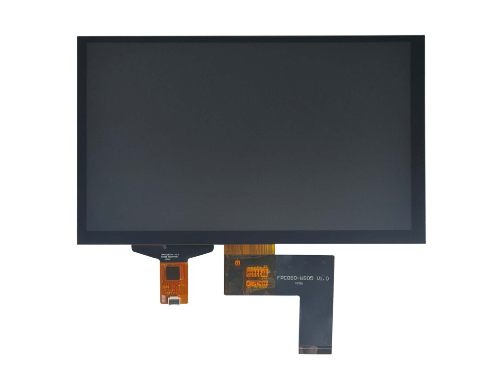
Which initialization steps belong in the kernel driver?
Power, reset and DSI initialization belong in the driver.
The kernel driver should own rail sequence, reset timing, DSI host configuration and panel prepare and enable, leaving applications to request a mode.
A load switch such as the TPS22918 can change the rail rise and therefore the reset-relative timing the panel sees. The driver is the component that owns the panel’s power state. It should sequence the rails, release reset at the specified time, configure the DSI host for the lane count and format, send the initialization table and wait for the panel to become ready. It should also implement the reverse sequence on disable and the restore path on resume. Application code should not replay register writes or toggle GPIOs.
The DRM panel and bridge helpers describe the prepare, enable and disable responsibilities that the driver should follow. The exact call order depends on the kernel version and the panel driver, so the implementation should be checked against the documentation for the release in use. The DRM KMS documentation covers the broader pipeline and mode responsibilities.
Keep the vendor table in a versioned data file or a clearly separated source file, not inline in a probe function. That makes it reviewable, replaceable and testable when the panel revision changes.
How should command logs avoid exposing proprietary settings?
Share command names and status, not proprietary values.
A public log can state which command failed and the status returned, but vendor register values, gamma tables and timing data should be redacted.
Bring-up logs are routinely pasted into tickets, forums and supplier emails. A full register dump can disclose vendor-specific gamma, power and timing settings that the panel or driver supplier considers confidential. It can also be misleading, because a value that looks wrong without the surrounding table may be correct in context.
A safer log records the command name or opcode, the payload length, the status, the timestamp and the stage of the sequence. It can include the panel revision and the table revision without exposing the values. If a supplier needs the full dump to investigate, send it through the agreed channel and under the applicable agreement.
Redaction should be deliberate, not an afterthought. Define which fields are public, which are shared under agreement and which are never shared. That classification belongs with the initialization package, so the same rules apply to every engineer who handles a log.
What makes an initialization package reproducible?
Pin revision, sequence and test record in the package.
The package should include panel revision, initialization file and checksum, tool version, delays, validation results and a change log, so another team can reproduce it.
A package is reproducible when another engineer can take it, apply it to the same build and obtain the same result. That requires the panel revision, the initialization file and its checksum, the driver and tool versions, the delay values, the host configuration and the validation record. It also requires the test conditions: temperature, supply voltage, pattern and the point at which the first valid frame was observed.
The package should be stored with the build, not in an individual’s workspace. If the table is a binary blob, include the source document and the revision it came from. If it is a source file, include the commit identifier. A change log should state what changed, why and which units were validated.
The table below is the minimum record for a bring-up handoff. It is a template, not a set of limits; the limits come from the panel document and the host datasheet.
| Signal or rail | Power state | Trigger or capture point | Observed behavior | Source of acceptance limit |
|---|---|---|---|---|
| Panel supply rails | Off to on | Connector pins | Ramp order and settling | Panel drawing |
| Reset | Asserted to released | Panel reset pin | Release relative to rails | Panel drawing |
| DSI clock and data lanes | LP to HS | Panel connector | Training and first command packet | Host datasheet, panel drawing |
| DCS sleep-out | Command | Host driver log and bus | Command accepted and delay measured | Panel command table |
| Display-on | Command | Host driver log and panel output | First valid frame | Panel command table |
| Backlight enable | Off to on | Driver enable pin | Delay after first frame | Panel drawing |
The SN65DSI83 datasheet is an example of a bridge that has its own initialization and enable timing; a bridge-stored sequence is still a versioned artifact. Keep the bridge firmware revision in the package as well, because a bridge update can change the order in which the panel sees commands.
FAQ
Can an initialization table from a visually identical panel be reused?
No. Two panels can look identical and differ in the driver IC, the gamma curve, the power timing or the vendor command set. Reusing a table from a similar module can produce a working image with the wrong colour, an unstable power sequence or a failure at temperature. The table must be traceable to the exact panel revision.
Should panel register dumps be stored in public bug reports?
Usually not. A dump can contain vendor-specific gamma, timing and power settings that are confidential to the panel or driver supplier. Share the command names, the failing status and the timing evidence publicly, and exchange the full register values under the applicable agreement or in a private channel.
What should happen if the panel revision cannot be identified?
Treat the unit as unqualified. Without a revision, the initialization table, the delay values and the gamma settings cannot be matched to the build, and a failure cannot be compared with a known baseline. Ask the supplier for the revision and the corresponding table, or return the unit for identification before writing a sequence for it.
If a DSI panel bring-up needs the initialization table, delays and revision record aligned, send the panel revision and current sequence to the CDTech engineering team for a specification review.
Related articles
Touch Screen Grounding: Debug Floating and Earth-Referenced Installations SeparatelyCustom Displays, Sourcing & ManufacturingCapacitive Touch Glove Thickness: Validate Material and Fit Before Setting SensitivityCustom Displays, Sourcing & ManufacturingCapacitive Touch Water Rejection: Distinguish Droplets, Films and Flowing WaterCustom Displays, Sourcing & ManufacturingCapacitive Touch Charger Noise: Correlate Raw Data with Power-Supply ConditionsCustom Displays, Sourcing & Manufacturing