LVDS Signal Integrity: Isolate Reflections Across FPC and Connectors
LVDS signal integrity guide: treat connector and flex as one channel, use TDR to locate reflections and verify return paths before tuning termination.

LVDS signal integrity problems rarely look like a channel issue at first. An LVDS link that works on a short bench cable and shows fine colour noise in the enclosure is usually not a panel fault. The channel has changed: the production flex is longer, the connector adds a launch, and the return path may be incomplete. This guide treats the connector and flex as one channel, shows when to move from continuity to time-domain measurements, and defines the interconnect data that should be released with the design.
Where does LVDS signal integrity fail along the cable?
Mismatch appears at connectors, flex transitions and stubs.
Every change in geometry, dielectric or reference plane changes impedance: connector launch, flex stiffener, via, unused branch or a cable of the wrong impedance.
An LVDS channel is a controlled differential impedance from the transmitter to the receiver. Any place where the geometry, dielectric or reference plane changes can create a local impedance different from the design value. The connector launch, the transition from PCB to flex, the stiffener under the flex, a via, an unused branch and a cable that is not the specified impedance are all candidates.
The reflections from those discontinuities travel back toward the transmitter and forward toward the receiver, where they can distort the eye. A small discontinuity may be invisible at low rates and become significant at the product’s lane rate. The effect also depends on the rise time: a faster edge contains more high-frequency content and reflects more from a given discontinuity.
The TI LVDS owner’s manual covers the differential signalling and channel concepts behind these effects; the specific impedance target comes from the transmitter and panel documents and the board stack-up.
How should the connector and flex be treated as one channel?
Treat connector and flex as one continuous channel.
Connector and flex are not separate in the signal path; their launches, grounds and impedance must be designed and measured as one channel.
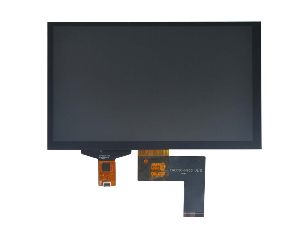
A connector is not a transparent junction. Its pins, plastic body and launch geometry change the impedance, and its ground pins determine how the return current crosses from the board to the flex. The flex adds its own dielectric and trace geometry, and the stiffener changes the local impedance. The receiver sees the sum of those effects, not a series of independent components.
Design and measure the channel as a whole. A connector that is excellent on its own can create a discontinuity when paired with a flex whose launch is different. A flex that is correct on its own can fail when the connector’s ground pins are not placed near the pair. The channel drawing should show the pair, the ground return, the connector pins and the flex stack-up as one path.
The TI guidance on LVDS impedance and termination is a starting point for the channel and termination; it does not replace the connector and flex datasheets.
Which symptoms justify time-domain measurements?
Ringing, eye closure or intermittent errors justify TDR.
Continuity can pass while the channel reflects; time-domain reflectometry shows where impedance changes and whether the reflection reaches the receiver.
Continuity and resistance measurements describe the conductor, not the channel. A pair can be continuous and still reflect. The symptoms that justify a time-domain measurement are ringing on the edge, overshoot or undershoot, a closed eye at the receiver, intermittent pixel errors that change with cable movement, and colour noise that appears at a particular resolution or refresh.
Time-domain reflectometry sends an edge into the channel and displays the reflections against distance or time. A discontinuity appears as a change in the trace, and its position can be related to the connector, the flex or a via. The measurement can be made with a dedicated TDR or with a scope and a fast edge, depending on the equipment available.
A TDR trace is only as good as its launch. Use the same connector and fixture as the product, or the reflection you see may belong to the probe. Record the rise time, the probe or fixture, the reference impedance and the cable length. A TDR result without those parameters is hard to compare with another measurement or with a simulation.
What can a shorter reference cable prove?
A short reference cable separates cable loss from launch.
A short known-good cable removes most cable loss; if the image improves, the cable or its length is the problem, not the transmitter.
A shorter cable is a controlled reference. It reduces loss and reflection delay, so a link that fails with the production cable but passes with the short one is sensitive to the channel. The result points to cable length, cable impedance, connector loss or the routing inside the enclosure.
The reference cable must be known good and must match the pair count and impedance of the production cable. A short cable with a different construction proves only that the link can work with that cable; it does not isolate the production cable’s contribution unless the two are otherwise comparable.
Record the reference cable’s length, part number and measured loss. A result described only as “with a short cable” cannot be reproduced.
How should return-path discontinuities be checked?
Check the return path at every connector and flex.
A pair needs a continuous reference; a missing ground pin, split plane or shield used as the only return creates a discontinuity and common-mode noise.
The differential pair carries signal current, and the return current must follow a controlled path close to the pair. A missing ground pin at the connector, a split in the reference plane, a flex with insufficient ground traces or a shield used as the only return all force the return current into an uncontrolled path. The result is a local impedance change and common-mode noise that can radiate or couple into other signals.
A split plane under the connector is easy to miss because the continuity check still passes; the return current detours around the split. Inspect the connector pinout and the flex drawing for ground pins adjacent to each pair. Check the board for plane splits under the connector and along the route. Measure the common-mode content at the receiver if the equipment allows; a rise in common-mode noise often accompanies a return-path problem.
The shield is not a substitute for the return. It can reduce emissions, but it does not provide the close, controlled return that the differential pair needs.
When does termination adjustment require device guidance?
Change termination only with the device datasheet in hand.
Transmitter and receiver datasheets define termination and fail-safe bias; a value copied from another link can reduce margin or violate the driver load.
Termination is not a universal resistor value. The transmitter has a specified load, the receiver may have an internal termination, and the link may require AC coupling or a fail-safe bias. A value copied from another LVDS link can be too low or too high, reducing the eye or exceeding the driver’s current capability.
The device datasheets define the allowed range and the recommended circuit. The board stack-up and connector determine whether the physical resistor can be placed close enough to the receiver to be effective. A termination placed after a long stub does not terminate the stub.
Record the termination value, its location and the device document that specifies it. If the value is changed during bring-up, record the change and the measured effect.
Which environmental cases challenge a marginal channel?
Temperature, vibration and bending stress a weak channel.
A channel that passes on the bench can fail when the flex bends, the connector wears or temperature changes dielectric and contact resistance.
A marginal channel has little margin to lose. Temperature changes the dielectric constant and the conductor resistance, which shifts the impedance and the loss. Vibration and repeated bending fatigue the flex and the connector contact, and a bend near the connector can change the local geometry. Humidity can change the flex surface and the connector insulation.
A cable that is flexed during the measurement can show a change in loss that is invisible when it lies flat. Test the channel in the assembled enclosure, with the production cable route and the connector mated as it will be in service. Flex the cable through its specified range and repeat the eye or error measurement. Run the temperature corners with the panel and the cable at the same temperature as the product.
A bench-only pass is not evidence for a product that moves, bends or heats. Record the environmental conditions with the result.
What interconnect drawing and test data should be released?
Release the stackup, pinout, TDR and eye data together.
The drawing should include pair assignment, impedance target, reference planes, connector and flex stackup, plus TDR and eye measurements at the panel.
The release package should let a new cable or connector be evaluated against the approved channel. A drawing without the measured data is a plan, not an approved channel. Include the pair assignment, the impedance target and tolerance, the reference plane and ground pin arrangement, the connector part and orientation, the flex stack-up and the bend radius. Add the TDR trace, the eye measurement and the test conditions.
Record the measurement points: at the transmitter, at the connector and at the panel. A result at the transmitter does not describe the panel’s input. If the production cable differs from the tested one, the package should state which measurements still apply and which must be repeated.
The table below is a template for the interconnect record. It is not a set of limits; the values come from the devices and the channel design.
| Flex channel | Impedance and loss | Stack-up, stiffener and bend | TDR and insertion loss | Approved if eye remains open |
| Panel input | Receiver termination | Connector and final length | Eye at panel | Approved if margin remains |
| Return path | Continuous reference | Ground pins and plane | Common-mode measurement | Approve only if continuous |
The DS90C385A datasheet is an example of a transmitter with device-specific output and timing limits; a bridge such as the SN65DSI83 adds its own output stage. The DRM KMS documentation covers the pipeline context in which the link is configured. The display and touch solutions centre shows how the interconnect decision connects to the module and assembly design.
FAQ
Can a continuity test detect an impedance discontinuity?
No. Continuity proves that the conductor is connected, not that its impedance is constant. A pair can pass continuity and still have a connector launch, a flex stiffener or a branch stub that reflects energy. Time-domain reflectometry or an eye measurement is needed to see the discontinuity.
Should a successful short-cable test authorize the final cable length?
No. A short cable removes loss and reduces the reflection delay, so it can pass while the production length fails. The short cable is a diagnostic reference, not a qualification. The final length, connector and routing must be tested at the product’s corners.
Can a connector shield substitute for a missing signal return path?
No. A shield is not a controlled return for the differential pair. If the ground pins or reference plane are missing, the return current takes an uncontrolled path, which creates a discontinuity and common-mode noise. The shield can help with emissions, but it does not replace the pair’s return.
If an LVDS link shows ringing or colour noise only with the production cable, send the stack-up, connector pinout and TDR or eye captures to the CDTech engineering team for a channel review.
Related articles
Touch Screen Grounding: Debug Floating and Earth-Referenced Installations SeparatelyCustom Displays, Sourcing & ManufacturingCapacitive Touch Glove Thickness: Validate Material and Fit Before Setting SensitivityCustom Displays, Sourcing & ManufacturingCapacitive Touch Water Rejection: Distinguish Droplets, Films and Flowing WaterCustom Displays, Sourcing & ManufacturingCapacitive Touch Charger Noise: Correlate Raw Data with Power-Supply ConditionsCustom Displays, Sourcing & Manufacturing